
Description
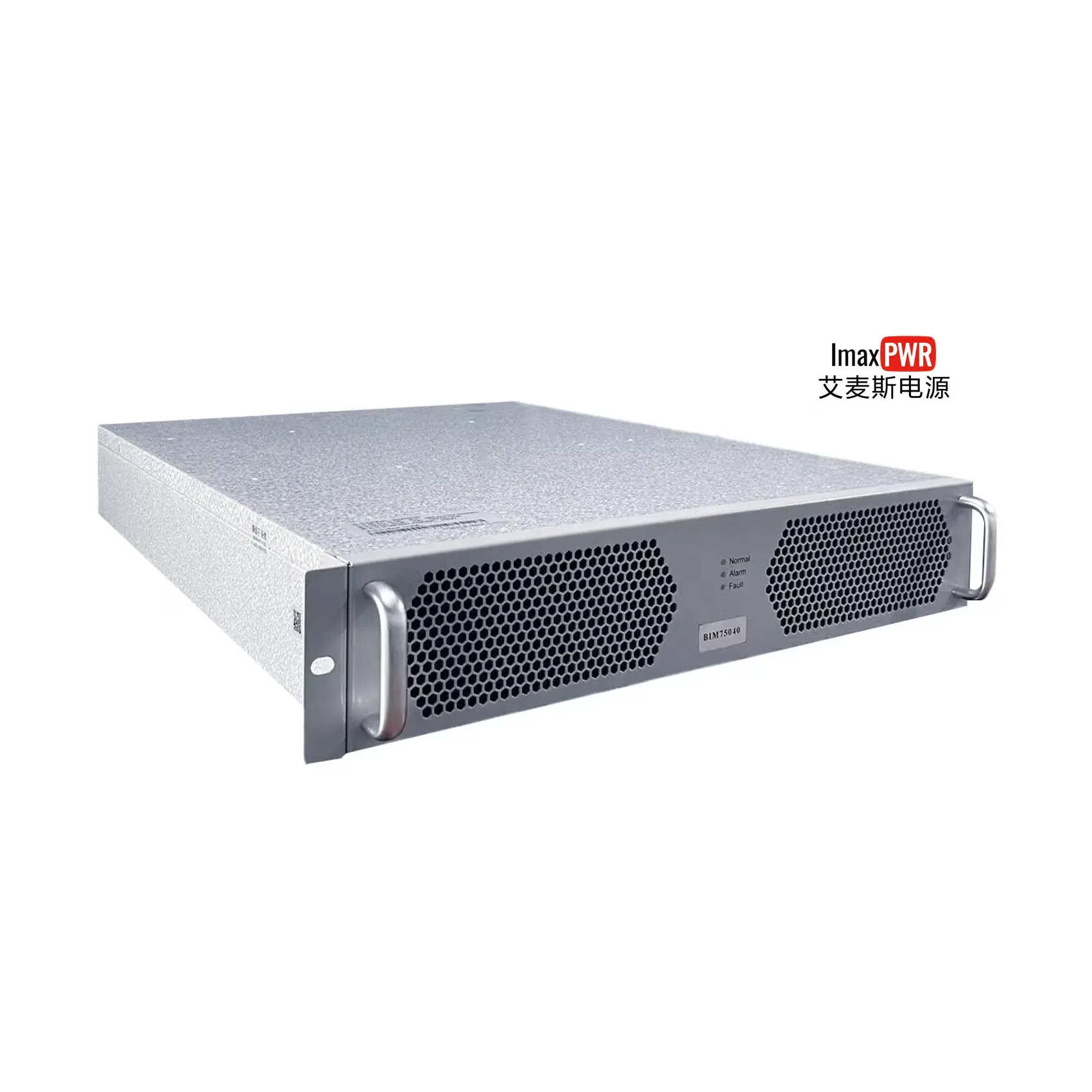
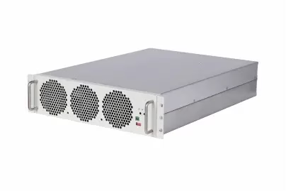
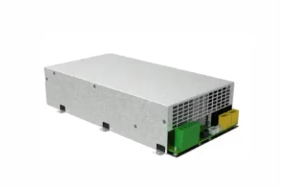
The BIM series 3000-3600-4200W is a multi-functional bidirectional PCS module, which adopts a high-efficiency soft-switching patented topology and digital control technology. It integrates a pure sine wave inverter, high-power charger, UPS bypass, RS485 and CAN communication ports, parallel operation and other functions.
Function Description:
- Standby Mode:
- The module is in standby state, waiting for instructions from the host computer.
- Automatic Working Mode:
- This mode supports automatic charging and discharging, with charging via the auxiliary path taking priority and grid-connected inversion taking precedence when off-grid.
- Charging State:
- When the auxiliary path is not activated, the battery charging power takes the value set by the host computer’s instruction power.
- If the auxiliary path is loaded, the host computer needs to calculate the remaining power for battery charging based on the current that the AC input cable can withstand.
- If the auxiliary path has no load, charge the battery according to the instruction power.
- Off-grid Inversion State:
- If there is no AC grid connection, supply power to the load through the auxiliary path and disconnect from the grid side.
- If the grid is connected or restored during the discharging process, and the voltages are equal or close, the auxiliary path can automatically switch to the grid connection, with the grid supplying power to the load. Meanwhile, the monitoring version needs to calculate the remaining power for battery charging based on the input current. If the voltages are not equal, inversion output takes precedence.
- DC Current Limit Point Adjustment:
- Can only be used in PCS charging mode. Adjusted via instructions sent by the host computer, it can be continuously adjusted with a minimum adjustment step of 0.1A. The DC current limit point is adjustable between 0~Max.
- DC Voltage Adjustment:
- Can be used in both PCS charging and inversion modes. Adjusted via instructions sent by the host computer, it can be continuously adjusted with a minimum adjustment step of 0.1Vdc. The DC voltage is adjustable between 40V-59.5V.
- Battery Over-discharge Activation:
- In the case where the matched battery over-discharge protection does not output, the PCS can realize the battery activation function. Specific measures: When the PCS detects AC power input and the voltage is within the normal range, if there is no communication within 5 seconds, the PCS will automatically start up, set the maximum charging voltage to 40V and the charging current limit to 3A by itself, charge the battery, and wait for the host computer to wake up and send new charging instructions.
- Fan Control:
- The module is cooled by air. The fan speed is intelligently adjusted based on the ambient temperature and power to achieve energy saving and ultra-low noise. The current speed percentage can be read in real time.
- Output Power Limit Control:
- The bidirectional module has two working modes: rectification (charging) and inversion. The output power is the same in both modes.
Product Specification Parameters:
| Module Function | Model | BIM48-3000 | BIM48-3600 | BIM48-4200 |
|---|---|---|---|---|
| Output Function | ||||
| Inverter Power | 3000W | 3600W | 4200W | |
| Charging Power | 3000W | 3600W | 4200W | |
| Inverter Output Voltage | 100Vac, 110Vac, 120Vac, 220Vac, 230Vac, 240Vac (optional) | 220Vac, 230Vac, 240Vac (optional) | ||
| Inverter Output Frequency | 50Hz, 60Hz (optional) | |||
| Inverter | Overload Capacity | 100%<P<=110% peak power, duration 20s 110%<P<=125% peak power, duration 5s 125%<P<=150% peak power, duration 2s 150%<P<=200% peak power, duration 200ms |
100%<P<=150% peak power, duration 2s 150%<P<=200% peak power, duration 200ms 200% peak power |
|
| Output Waveform | Pure sine wave | |||
| ThdU | 3%@resistive load | |||
| Efficiency | Max.91.2%@120Vac, Max.93.5%@220Vac | Max.93.5%@220Vac | ||
| Start-up | Supports 6 units of wired parallel operation | |||
| Rectification (Charging) | AC Input Voltage | 90-264Vac | 176-264Vac | |
| AC Frequency Range | 47-63Hz | |||
| Maximum AC Input Current | 30A (放宽至30A,but system design needs to consider regulations, e.g., maximum AC input 15A in the US, domestic maximum AC input current set to 16A) | |||
| PF | 0.99@100%Load | |||
| ThdI | <5%@100%Load | |||
| Maximum Charging Current | 60A | 72A | 80A | |
| Charging Voltage Range | 40-59.5Vdc | |||
| Voltage Ripple | Max.700mV (0-20MHz) | |||
| Efficiency | Max.92.5%@120Vac, Max.94.5%@220Vac | Max.94.5%@220Vac | ||
| Charging Management | Managed by host computer | |||
| Ac Bypass Switching | Ac Bypass Current | Max.15A | ||
| Switching Time | Typical 20ms | |||
| Environmental Conditions | Operating Temperature | -25°C ~ +70°C, derating above 45°C | ||
| Storage Temperature | -40°C ~ +70°C | |||
| Relative Humidity | ≤95%RH, no condensation | |||
| Cooling Method | Forced air cooling | |||
| Altitude | 2000m, for altitudes above 2000m, derate by 1°C for every 200m increase in altitude. | |||
| Atmospheric Pressure | 79kPa ~ 106kPa | |||
| Response Time | Max.10S (from host computer sending instruction to output) | |||
| Leakage Current | Max.10mA | |||
| Insulation Resistance | Insulation resistance between DC part, AC part and outer casing, and between AC part and DC part ≥10MΩ | |||
| Noise | Max.58dB (1m) | |||
| Others | Insulation Strength | AC terminal to casing: 1500Vac/50Hz or 2120Vdc60S, no breakdown, no flashover, steady-state leakage current <10mA; AC terminal to DC terminal: 3000Vac/50Hz or 4240Vdc60S, no breakdown, no flashover, steady-state leakage current <10mA; DC terminal to casing: 500Vac/50Hz or 710Vdc60S, no breakdown, no flashover, steady-state leakage current <10mA; AC terminal to CAN or 485 terminal: 3000Vac/50Hz or 4240Vdc60S, no breakdown, no flashover, steady-state leakage current <10mA; DC terminal to CAN or 485 terminal: 500Vac/50Hz or 710Vdc60S, no breakdown, no flashover, steady-state leakage current <10mA; Casing to CAN or 485 terminal: 500Vac/50Hz or 710Vdc60S, no breakdown, no flashover, steady-state leakage current <10mA; |
||
| Grounding Resistance | Grounding resistance ≤0.1Ω, withstand current ≥50A | |||
| Safety Regulations | TBD | |||
| EMC | EN55032, EN55035, IEC61000-3-2, IEC61000-3-3, FCC | |||
| MTBF | 250KHrs, 25°C, 80% load | |||
| Weight | Max.4Kg |
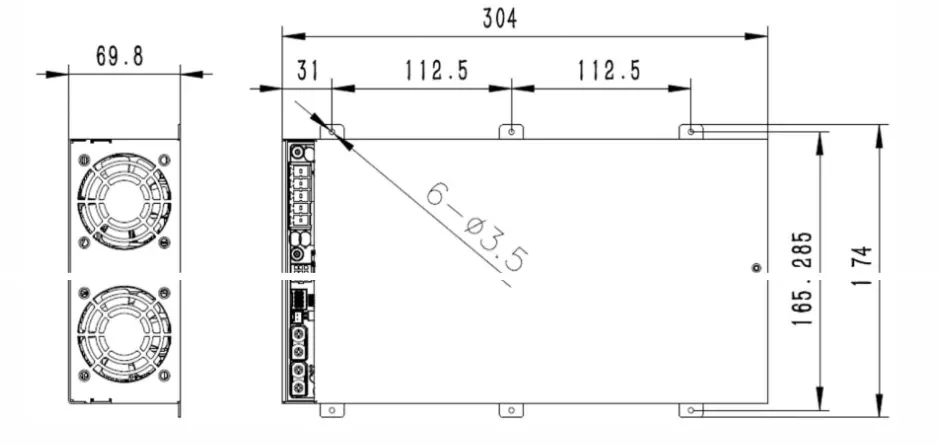
Installation Instructions: Module installation and fixation There are 3 installation holes on each side of the entire module. They are fixed by 3 M3 screws. The specific installation dimensions are shown in the following figure:
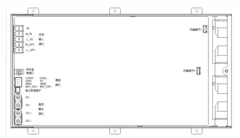 Module input/output terminal description: