

Description
Abstract
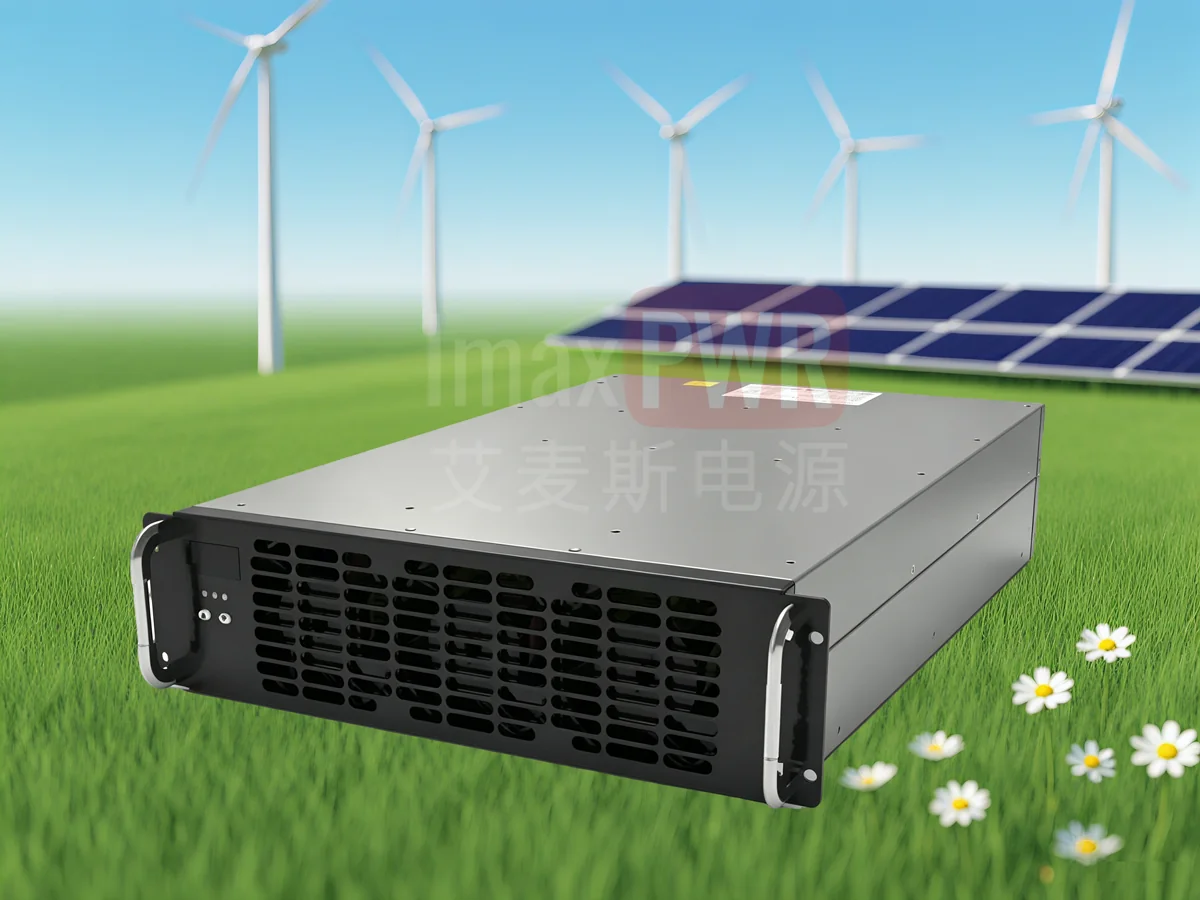
The ImaxPWR IMDC100040 is a 40 kW DC-input charging module engineered for the fast-growing PV-storage-charging segment. Unlike conventional AC-input modules that require an upstream rectifier stage, the IMDC100040 accepts a wide 250–825 Vdc DC bus directly, enabling a single-stage conversion from PV or battery DC to EV charging DC. It delivers an ultra-wide constant-power output of 200–1000 Vdc in high-voltage mode and 150–500 Vdc in low-voltage mode, reaching 97% peak efficiency and 60 W/in³ power density. With a -40°C to +70°C operating range, potting-grade protection, and support for up to 60 modules in parallel, it is built for DC microgrids, solar-storage-charging stations, and mobile charging systems in emerging markets where grid infrastructure is weak and ambient temperatures are high.
1. Product Positioning
The IMDC100040 occupies a distinct niche in the charging module landscape: it is a DC-input, DC-output (DC/DC) charging module rather than the more common AC/DC type. This architecture matters because an increasing number of charging stations are integrated with photovoltaic generation and battery energy storage on a shared DC bus. In such systems, converting PV DC to grid AC and then back to charging DC wastes energy and adds cost. The IMDC100040 eliminates that double conversion by drawing power directly from the 250–825 Vdc DC link.
According to the IEA Global EV Outlook 2025, electric car sales continue to grow rapidly worldwide, and public charging infrastructure — especially DC fast charging — must scale in parallel. Industry market analysis values the global DC fast charging power module market at approximately USD 2.5–4.2 billion in 2024–2025, projected to grow at a double-digit CAGR through the early 2030s, driven by EV adoption, 800 V vehicle platforms, and renewable-energy-integrated charging infrastructure. The IRENA Renewable Capacity Statistics further confirms that solar PV is the fastest-growing generation source, making PV-coupled charging an increasingly viable model. Within this market, DC-input modules are the preferred building block for mobile energy-storage charging stations and PV-storage-charging all-in-one systems where a common DC bus is the natural architecture.
Target customers include charging-station integrators, EPC contractors, microgrid designers, and OEMs building charging piles, charging containers, and PV-storage-charging cabinets. The module is particularly suited to projects in Southeast Asia, South Asia, the Middle East, Africa, and Latin America, where high ambient temperatures, weak or unstable grids, and abundant solar irradiance make DC-coupled PV-storage-charging the most cost-effective topology.
2. Product Overview & Working Principle
The IMDC100040 consists of two cascaded DC/DC conversion stages, an auxiliary power supply, input/output detection and protection circuits, and a DSP-based digital controller. A CAN bus handles communication between the module and the system controller as well as current sharing among paralleled modules.
The front-end DC/DC stage performs power-factor correction and bus voltage regulation for the DC input (an active PFC function adapted for DC sources), while the second-stage DC/DC provides galvanically isolated, tightly regulated output voltage and current to the EV battery. The dual-stage architecture allows the module to maintain constant power across an unusually wide output voltage range: in high-voltage mode it holds 40 kW from 200 V to 1000 V, and in low-voltage mode it delivers up to 80 A from 150 V to 500 V. This means a single module can charge both 400 V-class and 800 V-class EVs without derating in the mid-voltage band.
An LED display on the front panel shows real-time voltage, current, group number, protocol, address, manual/auto mode, and fault codes. Two navigation keys allow local parameter setup and mode switching. The module supports both automatic mode (fully controlled by the system monitor via CAN) and manual mode (local voltage/current setting with status still reported to the monitor), giving integrators flexibility during commissioning and service.
3. Technical Specifications
| Parameter | High-Voltage Mode | Low-Voltage Mode |
|---|---|---|
| DC Input Voltage | 250 Vdc – 825 Vdc | |
| Rated Output Power | 40 kW | |
| Output Voltage Range | 200 – 1000 Vdc | 150 – 500 Vdc |
| Rated Output Current | 40 A | 80 A |
| Current Limit Range | 0.5 – 80 A | 0.5 – 133 A |
| Efficiency | ≥95% rated; 97% peak; 96.5% full load @750 Vdc input | |
| Voltage Regulation Accuracy | ≤±0.5% | |
| Current Regulation Accuracy | ≤±1% | |
| Current Sharing Imbalance | ≤5% of rated output (10%–100% load) | |
| Max Parallel Modules | 60 units (per CAN group, G01–G15 groups) | |
| Operating Temperature | -40°C – +70°C (derating above 55°C) | |
| Cooling | Intelligent forced-air cooling (stepless fan speed) | |
| Communication | CAN (125 k / 250 k / 500 k baud selectable) | |
| Dimensions (W×H×D) | 84 × 300 × 437.5 mm (excluding panel & handle) | |
| Weight | ≤17 kg | |
| MTBF | 500,000 hours @40°C | |
| Standards & Compliance | IEC 61851-23:2014; IEC 61851-21-2:2021; EN 61000-6-1/2/3/4:2019; UL 2202; UL 2231; NB/T 33001-2018; NB/T 33008.1-2018 | |
Note: Parameters not specifying temperature or other conditions reference NB/T 33001-2018 and NB/T 33008.1.2-2018. Output performance in the 200–1000 V range meets national standards; 150–200 V supports normal charging without performance guarantee. Half-potting is the default shipping configuration.
4. Core Advantages
4.1 Direct DC Input Eliminates Double Conversion
In a conventional AC-coupled charging station, PV DC is inverted to AC, fed into the grid, and then rectified back to DC by the charging module — two conversion stages each incurring 2–5% loss. The IMDC100040 takes the 250–825 Vdc DC bus directly, performing a single isolated DC/DC conversion to the EV battery voltage. In a PV-storage-charging system this can improve end-to-end efficiency by 3–7 percentage points and reduce the required PCS rating, since the charging load no longer passes through the battery inverter. This architecture aligns with the engineering guidance in our DC-coupled vs. AC-coupled BESS engineering guide, where DC-coupled PV-storage-charging is recommended for high-renewable, weak-grid sites.
4.2 Ultra-Wide Constant-Power Output Covers 400 V and 800 V Platforms
Many charging modules on the market deliver full power only across a narrow voltage band (e.g., 300–500 V), forcing current reduction at both low and high battery voltages. The IMDC100040 maintains full 40 kW from 200 V to 1000 V in high-voltage mode — a 5:1 voltage range — and switches to low-voltage mode for 150–500 V at up to 80 A. This means a station built with IMDC100040 modules can charge legacy 400 V EVs, current 800 V platforms, and upcoming 1000 V-class vehicles without adding separate module types or suffering mid-voltage derating. Per IEC 61851-23:2014, DC EV supply equipment is rated up to 1500 Vdc, and the IMDC100040’s 1000 V output positions it well within the standard’s high-voltage charging envelope.
4.3 Wide Temperature Range & Potting Protection for Harsh Environments
The module operates from -40°C to +70°C ambient, with controlled linear derating above 55°C (down to 20 kW at 70°C in the most conservative curve). This is critical for deployments in the Middle East, South Asia, and Sub-Saharan Africa where cabinet internal temperatures can exceed 50°C under full sun. The half-potting (glue-pouring) construction — referred to as partial potting — improves vibration resistance, dust ingress protection, and thermal conductivity compared to non-potted modules. Intelligent forced-air cooling with stepless fan speed keeps noise below 68.1 dB(A) at full load and extends fan life by reducing average RPM.
4.4 High Power Density & Hot-Swap Design Reduce Cabinet Footprint
At 60 W/in³ and only 84 mm wide, the IMDC100040 packs 40 kW into a 3U-height rack slot. A standard 19-inch cabinet can accommodate multiple modules side by side, and the hot-swap design allows module replacement without powering down the entire charging station — a critical uptime requirement for commercial charging operators. Up to 60 modules can share a single CAN bus group for current sharing, and up to 15 groups (G01–G15) can be managed by one master controller, enabling multi-megawatt charging depots. The built-in anti-reverse-connection circuit and output voltage bleed-down circuit ensure safe hot-plugging even when the DC bus is live.
4.5 Comprehensive Protection & CAN-Based Remote Management
The module integrates short-circuit protection (with three-strike lockout), input over/under-voltage protection, output over/under-voltage protection (with four-strike lockout), over-temperature protection, fan-fault shutdown, and PFC bus over-voltage protection. All faults are reported over CAN with diagnostic fault codes (E00–E18) and displayed on the front LED panel. The system controller can remotely start/stop the module, switch equalization/float charging, and adjust voltage, current, and power limits in real time. This level of telemetry is essential for unmanned charging stations in remote areas and for integration with higher-level energy management systems such as ImaxPWR’s energy management platform.
5. Application Scenarios
5.1 PV-Storage-Charging All-in-One Stations
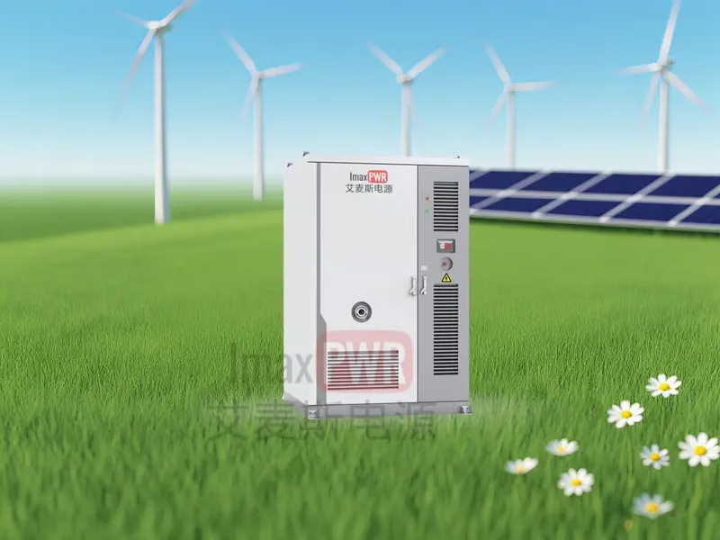
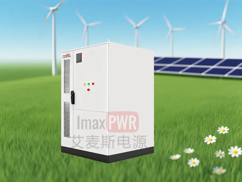
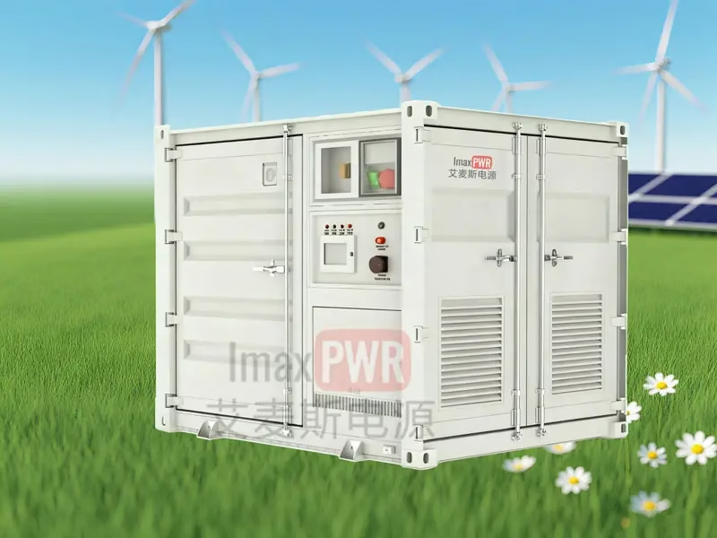
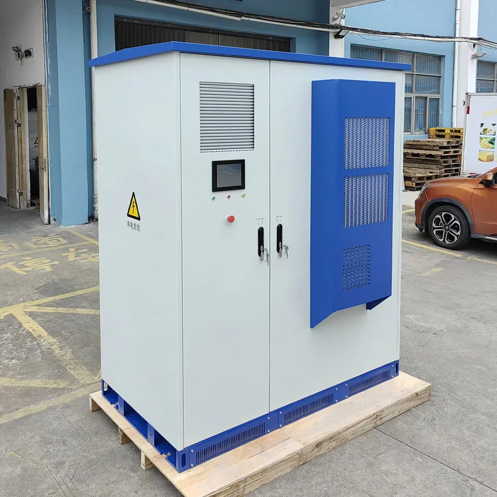
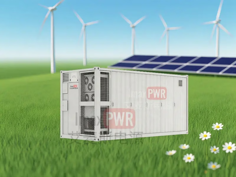
In a PV-storage-charging all-in-one cabinet, a PV array and a battery pack share a common 750–825 Vdc bus. The IMDC100040 draws directly from this bus to charge EVs, while a bidirectional DC/DC (such as the ImaxPWR BIDC75050F 20 kW bidirectional DC/DC) manages battery charge/discharge. During midday solar peak, PV power flows directly to EVs; during evening peak, the battery discharges through the same DC bus to the charging modules. No grid-tie inverter is needed for the charging path, reducing cost and conversion loss. This topology is the core of ImaxPWR’s 125 kW / 200 kWh mobile charging station and can be scaled to stationary C&I charging hubs.
5.2 DC Microgrids & Off-Grid Charging
In remote areas, mining sites, island resorts, and agricultural hubs where the grid is absent or unreliable, a DC microgrid built around PV + battery + diesel backup can power EV charging directly. The IMDC100040’s 250–825 Vdc input range matches the typical DC bus voltage of such microgrids, and its -40°C to +70°C operating range handles both high-altitude cold and tropical heat. The CAN interface integrates with the microgrid EMS, allowing charging power to be throttled when PV generation drops or battery state of charge is low, preventing system blackouts.
5.3 Fleet Depots & Commercial Charging Hubs
For bus depots, logistics centers, and ride-hailing fleet charging hubs, the IMDC100040 can be deployed in high-density cabinets with 10–20 modules per cabinet, delivering 400 kW – 800 kW per cabinet. The 60-module parallel limit per CAN group supports multi-cabinet scaling to megawatt-level depots. Hot-swap replacement minimizes downtime, and the wide output voltage range handles both 400 V delivery vans and 800 V electric trucks. The module’s compliance with IEC 61851-23 (DC EV supply equipment) and IEC 61851-21-2 (EMC for off-board charging systems) ensures compatibility with international charging standards and simplifies certification for export projects.
6. System Integration & Cabling
Each module should be protected by an individual DC circuit breaker on the input side so that a single module fault does not take down the entire DC bus. The input connector uses two pairs of Vin+/Vin- terminals (7 AWG, 180°C, 1100 V UL3640 cable recommended), and the output connector provides VOUT+/VOUT- terminals (5 AWG recommended). A 120-ohm terminating resistor must be installed across CANH and CANL at the farthest module on each CAN bus segment for proper impedance matching and current sharing.
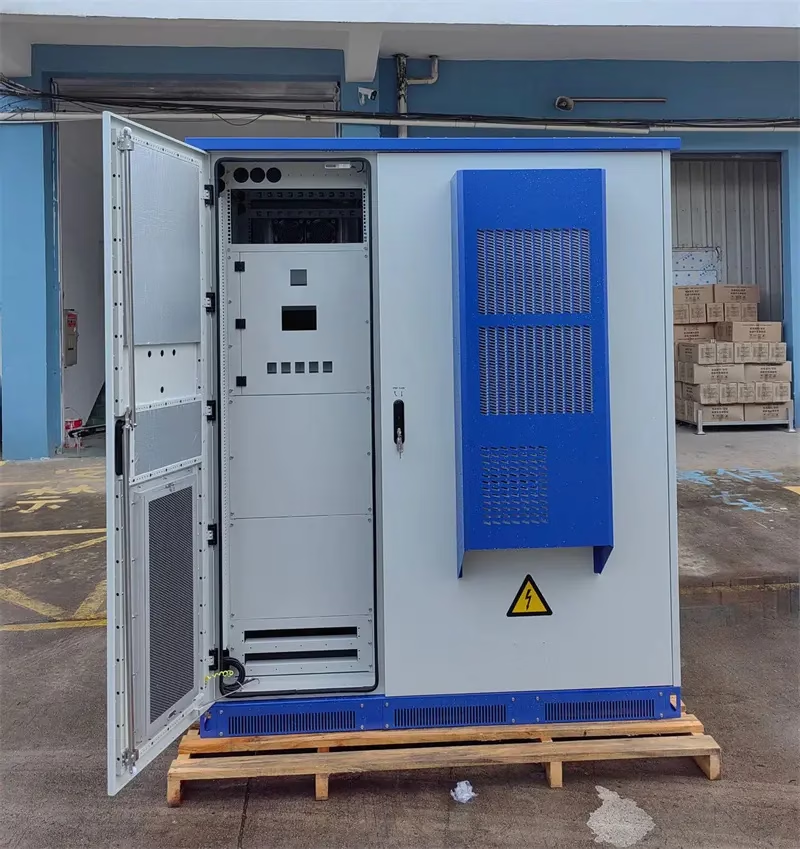
For thermal design, the module draws cooling air from the front and exhausts to the rear. System designers must maintain at least 100 mm clearance at the inlet and 80 mm at the outlet, with a minimum per-module ventilation area of 10,717 mm². In outdoor cabinets, inlet and outlet air ducts must be isolated to prevent hot-air recirculation, and an additional system exhaust fan is recommended. A dust filter at the cabinet inlet should be inspected and cleaned periodically to prevent airflow blockage and over-temperature derating.
7. Service & Delivery
ImaxPWR provides end-to-end support from system design to after-sales maintenance. Our engineering team assists with module selection, cabinet thermal design, CAN bus topology, and EMS integration. Standard warranty covers manufacturing defects; extended warranty and on-site service packages are available for large-scale projects. Spare modules are stocked for rapid replacement, and the hot-swap design means a trained technician can swap a module in under five minutes without specialized tools. For long-term storage (over 9 months), modules should be stored in dry packaging with desiccant and re-conditioned by running at 500 V no-load for 2 hours followed by light-load and full-load burn-in before commissioning.
8. Frequently Asked Questions (FAQ)
Q1: Can the IMDC100040 be used with a standard AC grid input?
No. The IMDC100040 is a DC-input module requiring 250–825 Vdc at its input. For grid-connected AC charging stations, ImaxPWR offers AC/DC charging modules such as the SEG series. The IMDC100040 is specifically designed for DC-coupled PV-storage-charging systems, DC microgrids, and battery-backed mobile charging stations where a DC bus is already present.
Q2: What is the difference between high-voltage mode and low-voltage mode?
High-voltage mode covers 200–1000 Vdc output at up to 40 A (40 kW constant power down to 200 V). Low-voltage mode covers 150–500 Vdc output at up to 80 A (and up to 133 A current limit setting), suited for lower-voltage battery packs. The mode is selected via the system controller or local panel, allowing a single hardware platform to serve both 400 V and 800 V vehicle platforms.
Q3: How many modules can be paralleled, and how is current sharing managed?
Up to 60 modules can be paralleled per CAN group (addresses A01–A60), and up to 15 groups (G01–G15) can share one master controller. Current sharing is implemented over the CAN bus, with a current-sharing imbalance of ≤5% of rated output current across 10%–100% load. A 120-ohm terminating resistor is required at the farthest module on each CAN segment.
Q4: Is the module suitable for outdoor installation in high-temperature or coastal environments?
The module operates from -40°C to +70°C with controlled derating above 55°C, and the half-potting construction improves dust and vibration resistance. However, the module itself is not IP-rated; it must be installed inside a charging cabinet with at least IP54 protection per GB/T 18487.1-2023 and NB/T 33001-2018. For coastal or high-humidity environments (corrosion class C4 or above, within 3 km of saltwater), additional anti-corrosion measures and more frequent maintenance are required; consult ImaxPWR engineering for site-specific guidance.
Related Products
Explore the full charging and power-conversion lineup: BIDC1K0135S2 40kW DC/DC Charging Module · IMAX1K075 V2G Bidirectional Charging Module · 125kW/200kWh Mobile Charging Station · BIDC75050F 20kW Bidirectional DC/DC · Charging Pile Category · Product Center
About the Author
Ethan Li, energy storage systems engineer at ImaxPWR Power Co., Ltd., focused on PCS, DC/DC converters, and microgrid design. This article was reviewed by Ethan Li.
About ImaxPWR
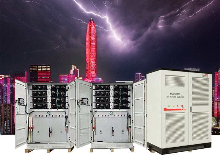
ImaxPWR Power Co., Ltd. (Brand: ImaxPWR) is a National High-Tech Enterprise and source manufacturer founded in 2019, headquartered in Shenzhen, China. We cover bidirectional converters, DC/DC modules, energy management systems, and energy storage cabinet integration, providing design, delivery, and O&M services for grid, microgrid, and charging-station scenarios. Our R&D team brings experience from State Grid, XJ Group, Emerson, and Kehua Tech. For PV-storage-charging and DC microgrid projects, we deliver integrated systems that pair the IMDC100040 charging module with our All-in-One ESS cabinets and hybrid PCS, reducing system handoffs and simplifying performance guarantees.
Designing a PV-storage-charging station or DC microgrid?
Request the full IMDC100040 datasheet, 3D model, or a customized system configuration. Our engineering team can help you size the DC bus, select module count, and integrate charging with PV and battery storage for maximum self-consumption and uptime.
Contact: COCO
Tel / WhatsApp: +86-13760212825
Email: info@imaxpwr.com
Website: https://imax-pwr.com
© 2026 ImaxPWR Power Co., Ltd. · This article is for product introduction purposes. Data sourced from the IMDC100040 product manual, IEC international standards, and industry public materials.