

Abstract
DC-DC converters and voltage regulators are the workhorses of PV-storage-charging systems, yet most field faults in these systems trace back to six repeatable causes: input overvoltage, over-temperature and derating, output voltage drift, communication loss, insulation breakdown in humid environments, and nuisance protection trips. This guide explains each failure mode, its root cause, the engineering design features that prevent it, and a maintenance checklist that catches it early. Battery storage was the fastest-growing power technology in 2025, with additions up about 40% to almost 110 GW, according to the IEA Global Energy Review 2026 — and every one of those systems contains DC-DC conversion that must stay operational for years. Understanding the fault signature is the fastest route to cutting downtime.
1. Technical Background — Where DC-DC Converters Sit in the System
A DC-DC converter regulates DC voltage between two ports: a battery bank or fuel cell on one side and a common DC bus on the other. In solar-storage-charging architectures, the converter couples PV, battery, and EV charging onto one DC bus, performing MPPT, charging control, and bidirectional energy transfer in a single power stage. A voltage regulator variant performs the same regulation function at lower power for control circuits and auxiliary loads. When the converter trips or drifts, the whole DC bus loses its anchor — charging stops, PV export is limited, and loads see voltage excursions.
Why this matters now: theIEA Global Energy Review 2026 reports battery storage capacity additions rose about 40% in 2025 to almost 110 GW, the fastest-growing power technology of the year, while solar PV additions surpassed 600 GW. Based onBloombergNEF’s December 2025 survey, lithium-ion battery pack prices fell to a record USD 108/kWh, making DC-coupled storage the default choice for many new projects in Southeast Asia, Africa, the Middle East, and Latin America — regions where ambient temperatures exceed 40°C and humidity is high, which is precisely where DC-DC hardware is stressed hardest.
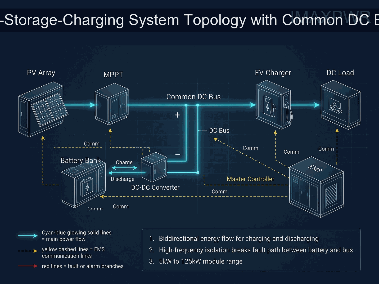
Figure 1 — PV-storage-charging topology: MPPT and DC-DC converters anchor the common DC bus that serves battery and EV charger.
2. The Six Common Faults and Their Root Causes
2.1 Fault 1 — Input Overvoltage from PV String Mismatch
The most common field failure we see is a converter with an MPPT input being fed an array whose open-circuit voltage exceeds the input rating on cold mornings. PV modules produce higher Voc at low temperature, and a string designed for hot-climate noon conditions can exceed the converter’s maximum input voltage at dawn. The failure signature is a persistent overvoltage trip at the input port, often logged as an OVP event. On the BIDC1500100 125 kW module, for example, the default overvoltage protection on the 1500 V port is 1570±20 V with fault lock and communication reset — the protection works, but a string above the rated window trips it repeatedly and blocks charging.
Root cause: string design used the array’s rated Voc instead of the temperature-corrected cold-morning Voc.Prevention: size strings so that Voc at the site’s record-low temperature stays below the converter’s maximum input voltage with margin; verify the MPPT window (e.g., 260–720 V on the BIDC75050F, 200–850 V on the M120KPV) against the array band before commissioning.
2.2 Fault 2 — Over-Temperature and Power Derating
DC-DC converters derate output power when internal temperature crosses the threshold. In hot-climate installations, the cause is usually restricted airflow: dust-clogged fan filters, converters mounted too close to cabinet walls, or a sealed cabinet with no ventilation. The failure signature is output power sagging exactly during peak solar hours — the opposite of what the site needs. Spec sheets make this explicit: the BIDC75050F operates from -40°C to +75°C with derating above 50°C, and the BIDC1500100 derates current above 40–45°C depending on voltage difference between ports.
Root cause: thermal management ignored at installation.Prevention: respect the clearance and airflow requirements in the manual, schedule fan filter cleaning, and use the converter’s reported internal temperature (available over RS485/CAN) to detect rising thermal resistance before power is lost.
2.3 Fault 3 — Output Voltage Drift and Regulation Error
A converter that “works” but regulates at the wrong setpoint silently degrades battery life. Voltage drift shows up as battery packs chronically under- or over-charged, or DC bus voltage sitting off-target. Modern digital converters hold tight tolerances — the BIDC75050F specifies voltage regulation accuracy within ±0.5% and load regulation within ±0.5%, and the BIDC1500100 specifies 0.5% voltage measurement and control accuracy at rated operating point. When drift appears, the cause is usually not the converter but the calibration reference: a drifted sensor, incorrect droop settings in parallel operation, or a misconfigured CV setpoint over the communication link.
Root cause: configuration or sensing error rather than hardware failure.Prevention: log the setpoint versus measured voltage at commissioning, verify the reference with a calibrated meter, and re-check droop coefficients when adding parallel units — the BIDC1500100 holds current imbalance below 7% in CV mode across up to 40 units.
2.4 Fault 4 — Communication Loss and Timeout Protection
DC-DC converters are commanded by an EMS or BMS over RS485, CAN, or Ethernet; when the link drops, the converter falls back to protection logic and often stops delivering power. Field causes are almost always wiring: RS485 A/B lines swapped, missing or wrong termination resistors, cables run alongside power cables, or a star topology on a bus that requires daisy-chain. The BIDC1500100 implements a communication fault protection with a default 0.5 s timeout — a brief EMS hiccup therefore becomes a hard stop unless the timeout is configured appropriately for the system.
Root cause: physical layer installation faults.Prevention: use shielded twisted-pair cable, terminate both ends of the bus, keep comm cables separate from power cables, and confirm polarity per the wiring diagram before energizing.
2.5 Fault 5 — Insulation and Leakage in High-Humidity Environments
High humidity plus condensation degrades creepage paths and can trigger insulation resistance alarms or leakage trips. This is the classic failure in coastal and tropical sites where equipment is installed in non-condensing-uncontrolled cabinets. Good design counters it with specified insulation resistance and withstand voltage: the BIDC75050F specifies insulation resistance of at least 10 MΩ between input/output and chassis and a 3535 V DC withstand test for 1 minute; the BIDC1500100 is rated for 3.5 kV basic and 4.4 kV reinforced insulation at 50/60 Hz for 60 s.
Root cause: condensation inside enclosures, damaged cable glands, or salt ingress.Prevention: install heaters or desiccant in humid cabinets, verify all glands are sealed, and include an annual insulation-resistance measurement in the maintenance plan.
2.6 Fault 6 — Nuisance Protection Trips (Surge and Inrush)
Converters are designed to clear real faults, but a poorly configured system trips on non-faults. Surge events from nearby lightning or switching, and inrush current when the DC bus is pre-charged, are the usual triggers. The BIDC75050F holds inrush current within 10% of rated current and passes surge, EFT, and ESD tests per its EMC specification; the BIDC1500100 integrates a fuse rated for fault currents of at least 100 kA at 1500 Vdc with an I²t limit below 50 A²s, and its protection thresholds are configurable over communication. If trips are frequent, check whether the thresholds match the site’s actual transient environment before suspecting hardware.
Root cause: transient environment harsher than the default protection settings assume.Prevention: review trip logs, adjust configurable thresholds where the vendor allows it, and add external surge protection at the DC bus if transient activity is documented.
3. Design Logic — What Prevents These Faults at the Source
The fault list above maps one-to-one onto design features a buyer can verify in a datasheet. High-frequency galvanic isolation breaks the fault path between battery and bus, so a fault on one side cannot propagate to the other. Soft-switching resonant topologies reduce switching loss and thermal stress, which is why modules such as the IMDC100100 reach 94% efficiency and the BIDC75050F exceeds 95.8% at 50–100% load. Dual digital control — DSP for the power loop plus CPLD for protection — separates fast protection from control logic, giving millisecond-class responses to overvoltage, overcurrent, and short-circuit events. Configurable thresholds over RS485/CAN let operators match protection to site conditions instead of living with factory defaults.
3.1 Protection Response and Closed-Loop Logic
A well-designed converter runs a closed loop: acquire voltage and current → judge against thresholds → execute power command or trigger protection → monitor and log → reset via communication. The BIDC1500100 shows the pattern concretely: overvoltage protection at 1570±20 V with fault lock and communication reset, undervoltage at 470±20 V, overcurrent at 105–120% for 20 s and above 120% within 0.1 s, and a current response time under 5 ms for a 0–90% step. These are the numbers to compare when evaluating vendors — not just efficiency, but how fast and how selectively the module clears faults.
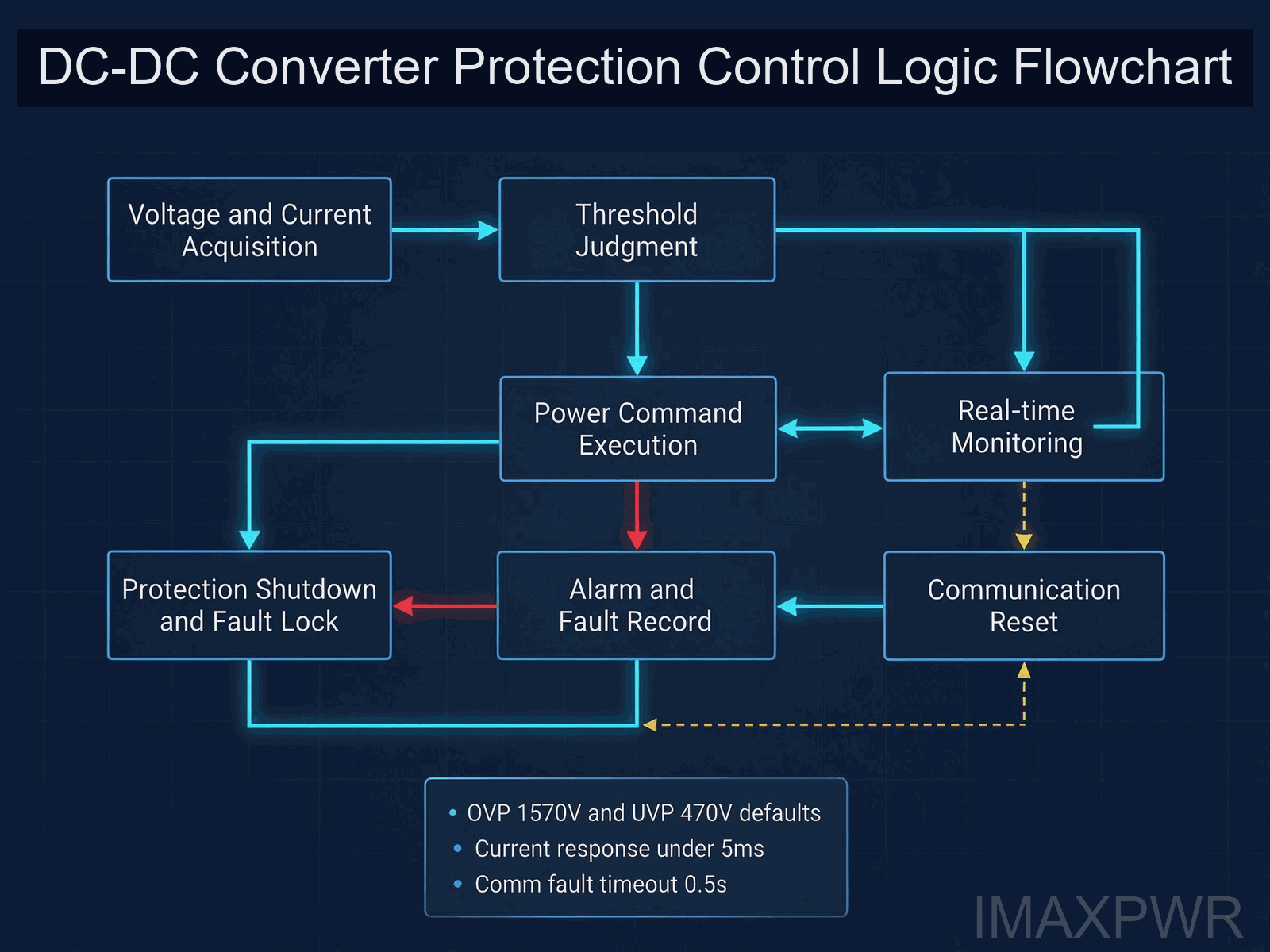
Figure 2 — DC-DC converter protection logic: normal branch runs closed-loop; abnormal branch triggers fault lock and alarm.
4. Errors and Optimization — Three Engineering Mistakes to Avoid
Error 1 — Ignoring altitude derating. Most converters derate above 2000–3000 m because thinner air cools less effectively. The M120KPV specifies operation up to 4000 m with derating above 2000 m; the BIDC1500100 derates above 3000 m. Installing a sea-level-sized system at 3500 m without de-rating the design power guarantees over-temperature trips in summer.
Error 2 — Communication wiring shortcuts. RS485 buses without termination, or daisy-chain loops built as stars, produce intermittent comm faults that are nearly impossible to diagnose remotely. Follow the vendor’s wiring rules, terminate the bus, and use the converter’s communication fault log to confirm stability before handover.
Error 3 — Sealed cabinets with no thermal path. IP-rated enclosures protect against dust and moisture but trap heat. Converters with forced-air cooling (all three modules covered here) need a defined airflow path; where the environment demands a sealed cabinet, specify a heat-exchanger or liquid-cooled variant instead of blocking the fans.
4.1 Technology Comparison — Isolated vs Non-Isolated vs Line-Frequency
| Dimension | HF Isolated Bidirectional DC/DC | Non-Isolated Bidirectional DC/DC | Line-Frequency Transformer Solution |
|---|---|---|---|
| Galvanic isolation | Full HF isolation, fault path broken | None — common-mode paths shared | Full LF isolation, bulky transformer |
| Typical efficiency | 95.8%+ (BIDC75050F); 94% (IMDC100100) | 99.2% max (BIDC1500100) | ~92-95%, constant core loss |
| Size and power density | Compact rack modules, 6.34 kW/L class | Compact, no isolation stage | Large and heavy, floor mounted |
| Fault containment | Best — battery and bus isolated | Faults share the DC bus | Good isolation, slow response |
| Cost and integration | Moderate — balances isolation and price | Lower per kW, needs system-level isolation | Higher logistics and install cost |
| Best-fit scenario | V2G, battery echelon, PV-storage-charging, fuel cells | High-power storage, 125 kW-class DC bus | Legacy industrial drives and grid interfaces |
The engineering conclusion from our projects: if the application needs galvanic separation between battery and bus — V2G, second-life batteries, fuel cells, or PV-storage-charging with mixed grounds — an HF isolated module is the right class despite slightly lower peak efficiency; if the application is a large common-DC-bus storage system with coordinated protection at system level, a non-isolated module with 99%+ efficiency such as the BIDC1500100 wins on energy throughput.
5. Technical Solution — Parameter Reference for Three Module Classes
The table below summarizes representative parameters across ImaxPWR’s DC-DC module range, giving a reference for troubleshooting thresholds and selection.
| Parameter | IMDC100100 (5 kW, HF Isolated) | BIDC75050F (20 kW, HF Isolated + MPPT) | BIDC1500100 (125 kW, Non-Isolated) |
|---|---|---|---|
| Battery-side voltage | 30-100 Vdc | 150-750 Vdc (output) | 500-1500 Vdc (rated 1250 V) |
| Bus-side voltage | 200-420 Vdc | 260-900 Vdc input (MPPT 260-720 V) | 500-1500 Vdc (rated 1500 V) |
| Max efficiency | 94% | 95.8%+ (conversion); 99.5%+ (MPPT) | 99.2% (above 1000 V) |
| Protection set | OVP, OCP, short-circuit, over-temp, reverse polarity | Multi-level, 3535 Vdc withstand, inrush ≤10% | OVP 1570V, UVP 470V, fuse ≥100 kA, I²t <50 A²s |
| Communication | CAN, RS485 | RS485, configurable thresholds | RS485, CAN, Ethernet |
| Parallel operation | DSP paralleling supported | Up to 16 modules | Up to 40 units, imbalance <7% CV |
| Temperature range | -40 to +60°C (derate above 55°C) | -40 to +75°C (derate above 50°C) | -25 to +45°C (current derating to 55°C) |
| Standards | UL1973, UL9540, GB/T 34120 | NB/T 33001 series EMC and safety | IEC 62477-1, UL 1741, IEC 61000-4 |
For safety-critical DC-coupled systems, perIEC 62477-1:2022 (safety requirements for power electronic converter systems and equipment, rated system voltage up to 1000 V AC or 1500 V DC), the converter’s insulation and protection design must be verified against the system voltage class; for grid-interactive projects in North American markets,UL 1741 covers inverters, converters, and charge controllers used with distributed energy resources. Ask for the certificate of the exact model, and compare protection thresholds and response times as seriously as efficiency.
6. Preventive Maintenance Checklist
- Quarterly: inspect and clean fan filters; verify internal temperature readings against ambient; check comm status and trip logs over RS485/CAN; confirm no fault-lock states pending.
- Semi-annual: measure insulation resistance between input/output and chassis (reference: ≥10 MΩ class); verify protection thresholds against site conditions; confirm battery-side and bus-side voltages match setpoints within the module’s stated accuracy (0.5% class).
- Annual: thermal imaging of the converter bay; firmware and configuration review with the vendor; inspection of glands, cabling, and torque on DC terminations; review of derating margin against the hottest recorded day.
- After any major transient event: retrieve trip logs, verify fuse and protection device status, and test operation under reduced load before returning to full power.
7. Industry Trends
Three trends shape DC-DC maintenance over the coming years. First, the 1500 V DC bus is becoming standard in large storage and PV-storage-charging systems, raising the stakes on insulation design and fault containment — the BIDC1500100’s 100 kA-class fuse and I²t limiting reflect that shift. Second, remote diagnostics are moving from optional to expected: converters with RS485/CAN/Ethernet and configurable thresholds let operators adjust protection and read fault logs without a site visit, cutting mean time to resolution. Third, the off-grid market keeps growing — based onIRENA’s Off-grid Renewable Energy Statistics 2025, off-grid renewable capacity reached 11.1 GW at the end of 2024 serving 86 million people, mostly in Africa, while theWorld Bank, IEA, and IRENA Tracking SDG 7 report (June 2026) still counts 655 million people without electricity — and DC-coupled equipment in these markets must survive heat, dust, and weak infrastructure with minimal skilled maintenance on site.
8. Author’s Perspective
In my years supporting DC-DC and PCS projects, I have rarely seen a converter fail from a single dramatic event. Most downtime is the accumulation of small system-design decisions: strings sized to the wrong temperature, cabinets that block airflow, communication cables run the easy way, and protection thresholds left at factory defaults for a site the factory never saw. The good news is that the same discipline that prevents these faults is cheap: read the derating table, respect the wiring rules, measure insulation annually, and keep the trip log as a living document. When you buy a converter, buy the one whose protection logic you can configure and whose fault behavior you can read — because in the field, a module you can interrogate is a fault you can fix in an hour, and one you cannot is a fault that takes a truck roll.
9. Frequently Asked Questions (FAQ)
Q1: Why does my DC-DC converter trip on overvoltage every cold morning?
PV strings produce higher open-circuit voltage at low temperature. Check the temperature-corrected Voc of your array against the converter’s maximum input voltage — e.g., the BIDC1500100 trips at 1570±20 V on its 1500 V port — and resize strings so cold-morning Voc stays below the rating with margin.
Q2: My converter derates output exactly at midday. What is wrong?
That pattern is over-temperature derating, typically blocked airflow or ambient temperature above the spec band. Clean fan filters, verify cabinet clearance, and read the module’s internal temperature over RS485/CAN — the BIDC75050F derates above 50°C and the BIDC1500100 derates current above 40-45°C depending on port voltage difference.
Q3: What accuracy should I expect from a digital DC-DC voltage regulator?
Well-designed modules hold voltage regulation within ±0.5% (e.g., BIDC75050F) and 0.5% voltage control accuracy at rated operating point (e.g., BIDC1500100). If measured voltage drifts beyond that, suspect setpoint configuration, sensor reference, or droop settings rather than the converter hardware.
Q4: Can I configure overvoltage and overcurrent thresholds on my converter?
On modules with communication-configurable protection, yes. The BIDC1500100 allows overvoltage, undervoltage, overcurrent, and over-temperature thresholds to be set and saved via communication, with fault-lock reset over the link; check the exact model’s capability before assuming thresholds are adjustable.
Q5: How often should I measure insulation resistance on a DC-DC converter?
At least annually, and more often in coastal or high-humidity sites. Reference insulation resistance is ≥10 MΩ between input/output and chassis (BIDC75050F class); a falling trend is an early warning of condensation or salt ingress before a leakage trip occurs.
Q6: My converter loses communication with the EMS intermittently. Where do I start?
Start with the physical layer: RS485 polarity, termination resistors at both ends, shielded twisted-pair cable separated from power cables, and no star topology on a daisy-chain bus. Note that modules such as the BIDC1500100 implement a default 0.5 s communication fault timeout, so wiring faults surface as hard stops.
Q7: What is the difference between isolated and non-isolated DC-DC for maintenance purposes?
Isolated modules break the fault path between battery and bus, so a fault on one side cannot propagate; they are the safer choice for V2G, second-life batteries, and mixed-ground systems. Non-isolated modules such as the BIDC1500100 reach higher efficiency (99.2%) but require system-level protection coordination on the shared DC bus.
Q8: What standards should a DC-DC converter for storage comply with?
For global projects, look for IEC 62477-1:2022 safety compliance and, for grid-interactive equipment in North America, UL 1741; EMC per IEC 61000-4 (and FCC Part 15 where applicable). Battery-facing modules may also carry UL 1973/UL 9540 references. Always request the certificate for the exact model number.
Related Reading:BIDC75050F 20 kW Isolated Bidirectional DC/DC with MPPT ·IMDC100100 5 kW Bidirectional Isolated DC/DC Module ·BIDC1500100 125 kW 1500 Vdc Bidirectional DC/DC ·Mobile Charging Station 125 kW/200 kWh ·8 C&I Energy Storage Architectures Guide ·AC/DC Coupled vs DC Coupled vs Hybrid BESS Engineering Guide ·ImaxPWR Product Center
About the Author
Ethan Li, energy storage systems engineer at ImaxPWR Power Co., Ltd., with years of experience in PCS, DC/DC converters, BESS, and microgrid design. He has participated in multiple domestic and international energy storage projects in solution design and technical support.
ImaxPWR is a National High-Tech Enterprise and a source manufacturer of integrated energy storage products and system solutions. This article was reviewed by Ethan Li.
About ImaxPWR
ImaxPWR Power Co., Ltd. (Brand: ImaxPWR) is a National High-Tech Enterprise and source manufacturer, covering bidirectional converters, DC/DC, energy management, and energy storage cabinet integration, providing design, delivery, and O&M services. Products are CE, UL, and ROHS certified. The DC/DC module family spans 5 kW to 125 kW, from 30 Vdc battery-side modules to 1500 Vdc bus-side converters, with high-frequency isolation and bidirectional energy flow for V2G, PV-storage-charging, and microgrid applications.
Dealing with a DC-DC fault or selecting a replacement module?
Send us the fault code, your battery and bus voltage levels, and the application — our engineers will help with the diagnosis and recommend a module that matches your protection and efficiency requirements.
Contact: COCO
Tel / WhatsApp: +86-13760212825
Email: info@imaxpwr.com
Website:https://imax-pwr.com
© 2026 ImaxPWR Power Co., Ltd. · This article is for engineering practice and maintenance purposes. Data sourced from industry public materials, international standards, and engineering practice.