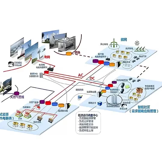


Note: This case study is based on typical project configurations and industry experience for illustrative purposes.
Project Background & Requirements
A mobile energy storage operator needed a dedicated DC fast charging station to recharge a 3,344 kWh mobile battery energy storage system (BESS). The mobile BESS — already specified by the customer — operates at 0.5C charge/discharge (1,672 kW), with a DC operating voltage range of 1,185.6 V to 1,497.6 V. The charging station had to be built around six 320 kW DC/DC converters.
The core requirements were:
- 6× 320 kW DC/DC converters as the charging power stage (total 1,920 kW — 15% redundancy over the 1,672 kW BESS charge rate).
- DC busbar convergence design — all six DC/DC outputs converge to a common DC bus before distribution to charging guns.
- At least 4 charging guns operating simultaneously — despite the battery being a single monolithic pack, the customer required multi-gun parallel charging.
- 380V / 50Hz auxiliary power supply for both the charging bay itself and the mobile BESS auxiliary systems (BMS, cooling, controls).
- Comprehensive system protection — insulation monitoring, over-current, short-circuit, over-voltage, under-voltage, and SPD surge protection.
- EMS with BMS communication — energy management logic, plug-and-charge gun-to-BMS handshake, and real-time battery state monitoring (SOC/SOH).
Key Engineering Challenges
1. Multi-Gun Parallel Charging of a Single Monolithic Battery Pack
The battery is one integrated pack — not four independent modules. Yet the customer requires at least four charging guns to work simultaneously. This creates a current-sharing problem: four guns connect to the same DC bus and the same battery terminals. Without active current sharing, one gun could sink disproportionate current while others idle, causing thermal imbalance, connector overheating, and potential BMS communication conflicts. The EMS must implement precise per-gun current allocation (approximately 418 kW / 280 A per gun at nominal voltage) and monitor each gun independently.
2. Wide Voltage Range (1,185.6V – 1,497.6V) and CC-CV Charging Transition
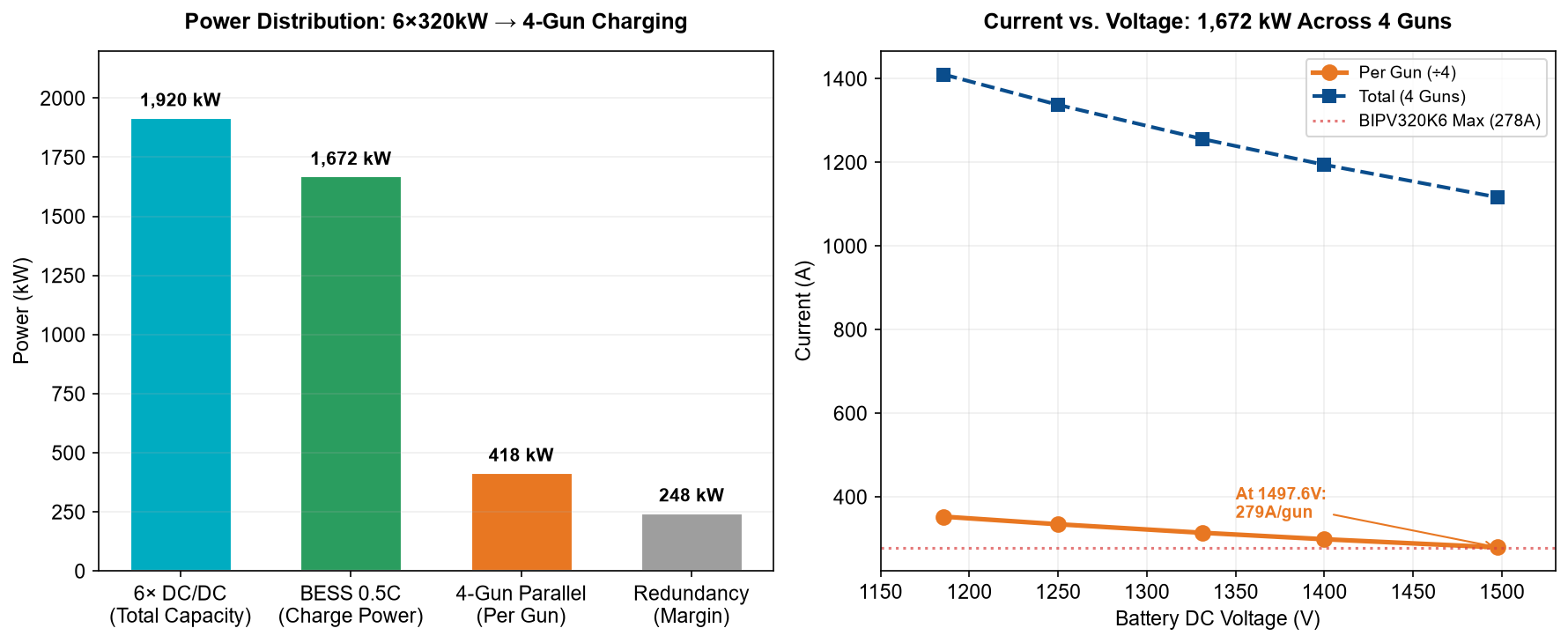
The BESS operates across a 312-volt swing (1,185.6 V to 1,497.6 V). At the low end, 1,672 kW requires 1,410 A total (352 A/gun); at the high end, only 1,116 A total (279 A/gun). The charging profile follows constant-current (CC) until the battery reaches its CV threshold (1,497.6 V), then transitions to constant-voltage (CV) with tapering current. The DC/DC converters must handle this full voltage range with high efficiency (>99%), and the EMS must smoothly manage the CC-to-CV transition without current overshoot or voltage spikes.
3. Auxiliary Power, Protection Coordination, and BMS Handshake
Three subsystems must work in lockstep: (a) a PCS generates 380V/50Hz AC auxiliary power for the charging bay and BESS auxiliaries — this must be stable even when the DC bus voltage fluctuates during charging; (b) six protection layers (insulation, over-current, short-circuit, over-voltage, under-voltage, SPD) must be coordinated so that a fault on one gun does not cascade to the entire station, while hardware-level fast protection (<10 µs) backs up software monitoring; (c) the EMS must perform a plug-and-charge handshake with the BMS via CAN/RS485 — verifying connector lock, insulation integrity, battery readiness, and then negotiating charge current/voltage setpoints before energizing the DC output.
Our Engineering Solution
System Architecture
Imaxpower designed a common-DC-bus architecture with six 320 kW DC/DC converters (BIPV320K6 wall-mounted hybrid MPPT controllers) feeding a shared 1,185.6–1,497.6 V DC busbar. From this bus, four independent charging branches — each with its own contactor (KA), fuse (FU), and charging gun — deliver power to the mobile BESS. A separate PCS taps the DC bus to generate 380V/50Hz AC auxiliary power. An EMS controller coordinates all energy flow, current sharing, protection logic, and BMS communication.
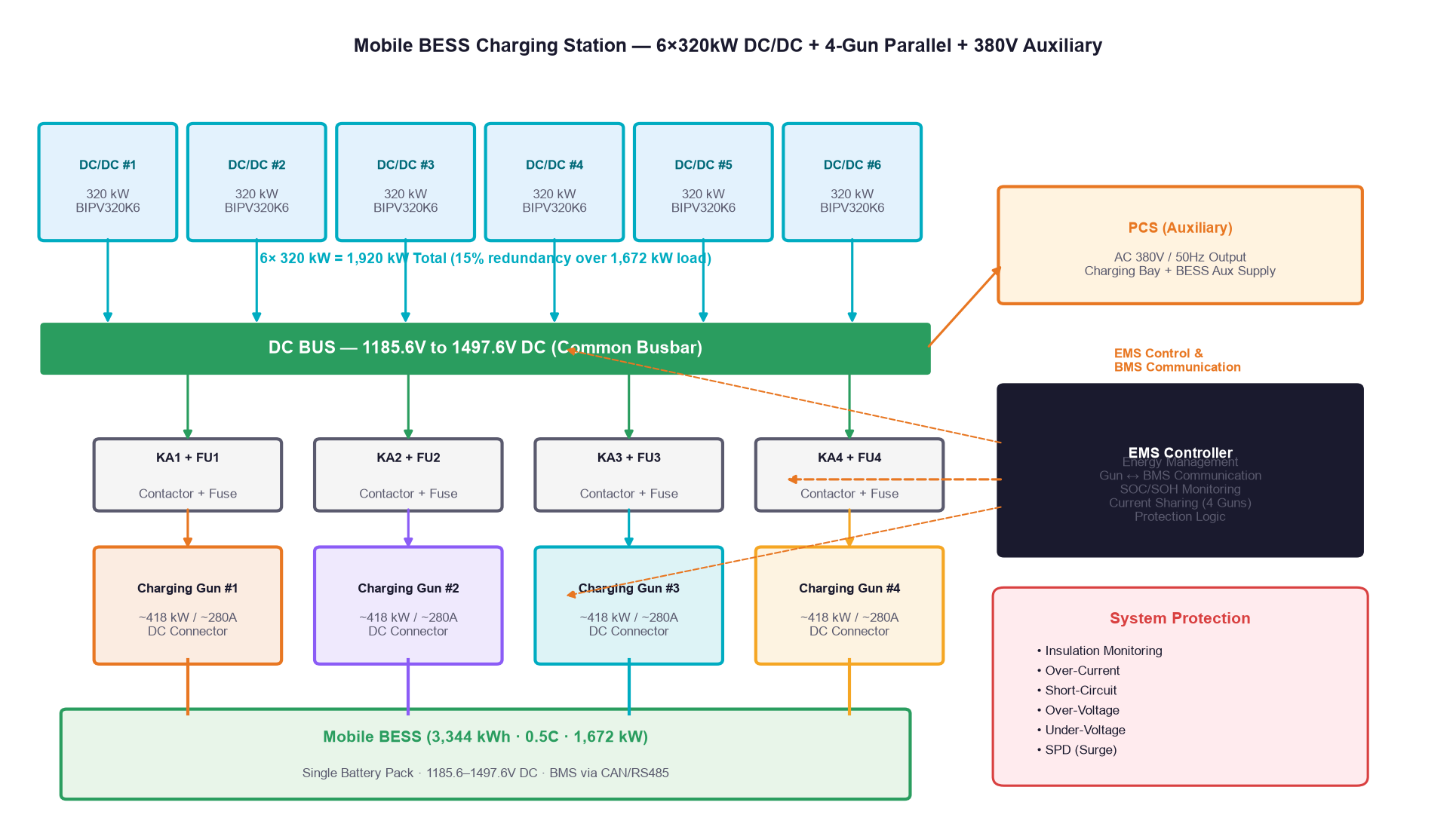
The 1,920 kW total DC/DC capacity provides a 15% margin over the 1,672 kW BESS 0.5C charge rate. This redundancy ensures that even if one DC/DC module is offline for maintenance, the remaining five (1,600 kW) can still deliver near-full charge power — no station downtime.
Component Selection
| Component | Selection | Key Specification | Engineering Rationale |
|---|---|---|---|
| DC/DC Converter | 6× Imaxpower BIPV320K6 | 320 kW, 240A rated / 278A max, 99.4% efficiency, IP66 | 6×320=1,920 kW total; 15% redundancy; high efficiency minimizes heat; IP66 for outdoor installation |
| Common DC Bus | Copper busbar, 1,500V rated | 1,185.6–1,497.6V operating, ≥2,000A capacity | Single convergence point for 6 DC/DC outputs; distributes to 4 guns; low-impedance busbar minimizes voltage drop |
| Charging Guns | 4× DC fast charge connectors | ~418 kW / ~280A per gun, 1,500V DC rated | 4-gun parallel meets customer requirement; current sharing via EMS; per-gun contactor+fuse for isolation |
| Auxiliary PCS | Imaxpower MSP100HKST (or equivalent) | 100 kVA, 380V/50Hz AC output, <10ms switch-over | Generates stable auxiliary power for charging bay + BESS; STS for seamless transfer if needed |
| EMS | Imaxpower full-stack self-developed | DSP+CPLD, CAN/RS485 BMS comm, cloud OTA | Current sharing (4 guns), CC-CV transition logic, plug-and-charge handshake, SOC/SOH monitoring, protection coordination |
| Protection | 6-layer coordinated system | Insulation, OCP, SCP, OVP, UVP, SPD | Hardware fast-acting (<10µs) + software monitoring; per-gun isolation prevents fault cascade |
Power & Current Distribution Strategy
With 1,920 kW of DC/DC capacity feeding a 1,672 kW load across four guns, the EMS implements active current sharing. At the nominal operating voltage (1,331.2 V), total current is approximately 1,256 A, or 314 A per gun — well within the BIPV320K6’s 278 A per-module maximum when considering that six modules share the total current (209 A per module). At the lowest voltage (1,185.6 V), total current rises to 1,410 A (352 A/gun, 235 A/module) — still within limits. At the highest voltage (1,497.6 V), current drops to 1,116 A (279 A/gun, 186 A/module).
Charging Profile: CC-CV at 0.5C
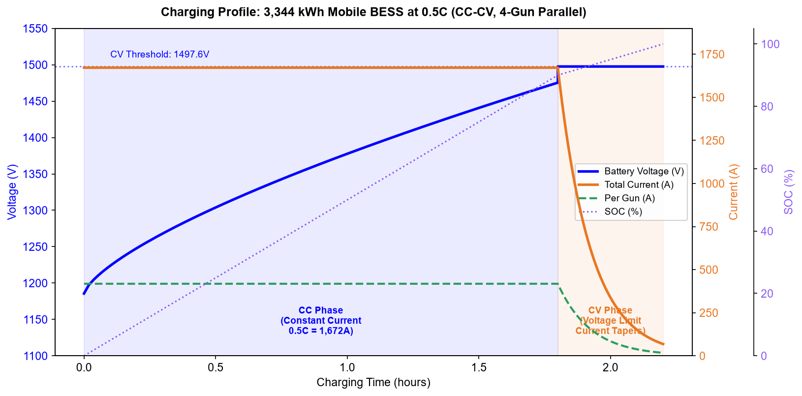
The 3,344 kWh mobile BESS charges at 0.5C (1,672 kW) following a standard CC-CV profile:
- CC Phase (0–90% SOC, ~1.8 hours): The six DC/DC converters deliver constant 1,672 kW total. Battery voltage rises from 1,185.6 V toward 1,497.6 V as SOC increases. Current per gun remains approximately constant (279–352 A depending on voltage).
- CV Phase (90–100% SOC, ~0.4 hours): Once the battery reaches 1,497.6 V, the EMS holds voltage constant and tapers current. Total current decays exponentially as the battery approaches full charge. The EMS reduces per-gun current proportionally to maintain balanced sharing.
- Total charge time: approximately 2.2 hours for a full 0–100% cycle at 0.5C.
Protection System Architecture
The station implements six coordinated protection layers, combining hardware-level fast response (<10 µs) with EMS software monitoring:
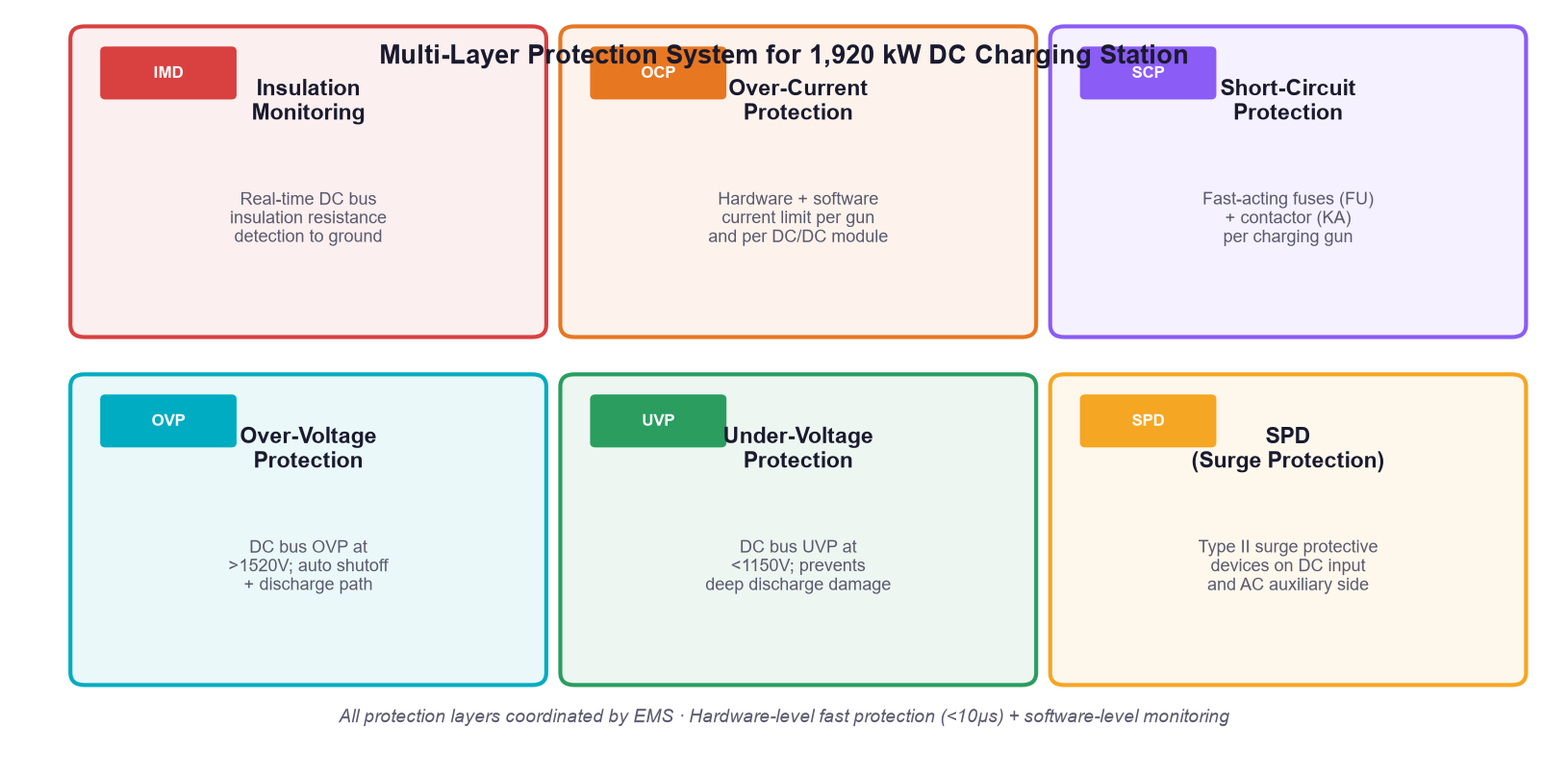
- Insulation Monitoring (IMD): Real-time DC bus insulation resistance to ground. Detects ground faults before they escalate. Triggers alarm at threshold, shutdown at critical.
- Over-Current Protection (OCP): Per-module and per-gun current limiting. Hardware comparator trips at 110% rated current within 10 µs. EMS software provides graduated current reduction before hard trip.
- Short-Circuit Protection (SCP): Fast-acting fuses (FU) per charging gun + contactor (KA) for galvanic isolation. A short on one gun blows its fuse and opens its contactor — the other three guns continue operating.
- Over-Voltage Protection (OVP): DC bus over-voltage at >1,520 V. Auto shutoff of all DC/DC outputs + controlled discharge path. Protects battery and DC bus components.
- Under-Voltage Protection (UVP): DC bus under-voltage at <1,150 V. Prevents deep discharge damage and unstable operation. Triggers controlled shutdown and BMS notification.
- SPD (Surge Protective Device): Type II surge arresters on DC input side and AC auxiliary side. Protects against lightning-induced transients and switching surges.
How to Select the Right Configuration
When designing a mobile BESS charging station, the key decisions are DC/DC sizing, number of guns, and whether to include a PCS for auxiliary power:
| Design Factor | This Project | Alternative | When to Choose Which |
|---|---|---|---|
| DC/DC per module | 320 kW (BIPV320K6) | 120 kW (BIPV120K4) or 60 kW (BIPV60K2) | 320 kW for high-power stations; smaller modules for distributed/modular designs |
| Number of modules | 6× (1,920 kW total) | 4× (1,280 kW) or 8× (2,560 kW) | Size for BESS charge rate + 10–15% redundancy; more modules = more N+1 redundancy |
| Charging guns | 4× parallel | 2× or single high-current gun | Multi-gun for connector flexibility and redundancy; single gun for simplest integration |
| Auxiliary power | PCS (DC→AC 380V) | External grid supply or separate UPS | Use on-board PCS when no grid available; external supply when grid is reliable |
| Common DC bus | Yes (busbar convergence) | Per-gun independent DC/DC | Common bus for current sharing and redundancy; independent for simpler per-gun isolation |
Measured Results & Performance
| Metric | Design Value | Industry Benchmark | Notes |
|---|---|---|---|
| Total DC/DC capacity | 1,920 kW (6×320) | 1,600–1,800 kW typical | 15% redundancy over 1,672 kW load |
| DC/DC efficiency | > 99.4% | 97–98.5% | BIPV320K6 rated max efficiency |
| Voltage range | 1,185.6 – 1,497.6 V | 500 – 1,000 V typical | 1,500V-class platform for high-power low-current |
| Per-gun current (nominal) | ~314 A @ 1,331V | 200–250 A typical | 4-gun parallel sharing |
| Full charge time (0.5C) | ~2.2 hours | 2–3 hours typical | CC + CV phases |
| Protection layers | 6 (IMD/OCP/SCP/OVP/UVP/SPD) | 3–4 typical | Hardware + software coordinated |
| Auxiliary power | 380V/50Hz via on-board PCS | External grid or separate UPS | Self-contained, no external AC needed |
| Protection rating (DC/DC) | IP66 | IP20–IP54 typical | Outdoor-rated, no climate room needed |
| BMS communication | CAN / RS485, plug-and-charge | Manual configuration typical | Auto handshake on connector lock |
Project Note: In a comparable mobile BESS charging deployment (4× 250 kW DC/DC, 2 MWh mobile BESS, 2-gun parallel), the station achieved 99.2% average DC/DC efficiency across 500+ charge cycles, with zero protection-related downtime. The 4-gun current sharing maintained ±2% current imbalance across guns, and the plug-and-charge BMS handshake completed in under 5 seconds from connector lock to energization.
Need a Similar System Design?
If you’re planning a mobile BESS charging station, DC fast charging infrastructure, or energy storage integration project, our engineering team can help you design the optimal system based on your specific BESS parameters, charge rate requirements, and site conditions.
Send us your project specs — BESS capacity, voltage range, charge/discharge rate, number of charging guns, auxiliary power requirements, and site ambient conditions — we’ll propose a solution within 24 hours.
Contact: info@imaxpwr.com | Tel/WhatsApp: +86-13760212825 | www.imax-pwr.com
Key Lessons Learned
- Always size DC/DC with 10–15% redundancy. The BESS charge rate is the floor, not the target. Redundancy covers module maintenance, voltage derating at high temperature, and future BESS upgrades.
- Common DC bus is essential for multi-gun parallel charging. Without a shared busbar, per-gun independent DC/DC cannot dynamically reallocate current if one gun is disconnected or faulted. A common bus gives true N+1 flexibility.
- Per-gun contactor + fuse is non-negotiable. A short on one gun must not take down the entire station. Galvanic isolation via contactor + fast fuse ensures the other guns keep charging.
- Don’t overlook auxiliary power. The BESS needs 380V/50Hz for its BMS, cooling, and controls. The charging bay needs lighting, HVAC, and control power. An on-board PCS eliminates dependency on external grid — critical for remote/mobile deployments.
- Plug-and-charge BMS handshake prevents user error. Manual voltage/current configuration by operators leads to mistakes. Auto-negotiation via CAN/RS485 ensures the charging station always matches the BESS requirements — every time.
- 1,500V-class DC is the future for high-power mobile BESS. Higher voltage means lower current, smaller cables, less heat, and higher efficiency. The 1,185.6–1,497.6 V range is well within the 1,500V DC platform that Imaxpower’s BIPV320K6 and centralized PCS products support.
FAQ
Q: Can multiple charging guns charge a single battery pack simultaneously?
A: Yes, if all guns connect to a common DC bus and the EMS implements active current sharing. The battery sees the combined current from all guns as a single charge current. The EMS allocates current proportionally across guns (e.g., 418 kW/gun for 4 guns at 1,672 kW total), monitors each gun’s voltage/current independently, and ensures balanced sharing (typically ±2% imbalance). Per-gun contactors and fuses provide isolation if one gun faults. This is a standard architecture in high-power DC fast charging stations.
Q: Why use six 320 kW DC/DC converters instead of one large 1,920 kW unit?
A: Three reasons: (1) Redundancy — if one 320 kW module is offline, the remaining five deliver 1,600 kW (96% of full rate); a single 1,920 kW unit is a single point of failure. (2) Scalability — modular design allows phased deployment (start with 4 units, add 2 later) and easy capacity upgrades. (3) Logistics and maintenance — 320 kW wall-mounted modules (60 kg, IP66) install with standard equipment and can be swapped individually; a 1,920 kW centralized unit requires a crane, dedicated foundation, and full station shutdown for any maintenance. The BIPV320K6 at 99.4% efficiency also outperforms most large centralized converters.
Q: How does the EMS communicate with the BMS during plug-and-charge?
A: The sequence is: (1) Operator connects charging gun — connector lock sensor confirms physical connection. (2) EMS initiates insulation monitoring on the DC circuit — verifies no ground fault before energizing. (3) EMS establishes communication with BMS via CAN or RS485 — reads battery type, voltage range, max charge current, SOC, SOH, and any fault/warning flags. (4) EMS and BMS negotiate charge parameters — EMS proposes voltage/current setpoints based on BMS limits and station capacity; BMS confirms or adjusts. (5) EMS energizes DC output — ramps voltage/current gradually (no overshoot) to the negotiated setpoint. (6) Continuous monitoring — EMS updates setpoints dynamically as SOC increases (CC→CV transition), BMS sends real-time cell voltage/temperature data, EMS adjusts per-gun current sharing. The entire handshake from connector lock to energization typically completes in under 5 seconds.
About the Author
This article was reviewed by Ethan Li, an energy storage system specialist with experience in PCS, DC/DC converters, and charging infrastructure design. With a background in power electronics and field commissioning of DC fast charging stations and mobile BESS systems, Ethan focuses on translating high-power charging requirements into deployable, redundant, and safe system architectures.
About IMAXPWR
Imaxpower (Imax Power Technology Co., Ltd.) is a China national high-tech enterprise headquartered in Shenzhen, specializing in integrated energy storage products and system solutions. Founded in 2015, the company has delivered 999+ projects worldwide with a 99% customer recognition rate.
The R&D team comprises senior experts from State Grid, Xuji Group, Emerson, and Kehua Hengsheng, with 20+ years of power electronics experience. Imaxpower develops full-stack self-developed PCS, BMS/EMS, bidirectional DC/DC converters, MPPT controllers, and all-in-one BESS cabinets, covering 30 kW to 2 MW+ system deployments.
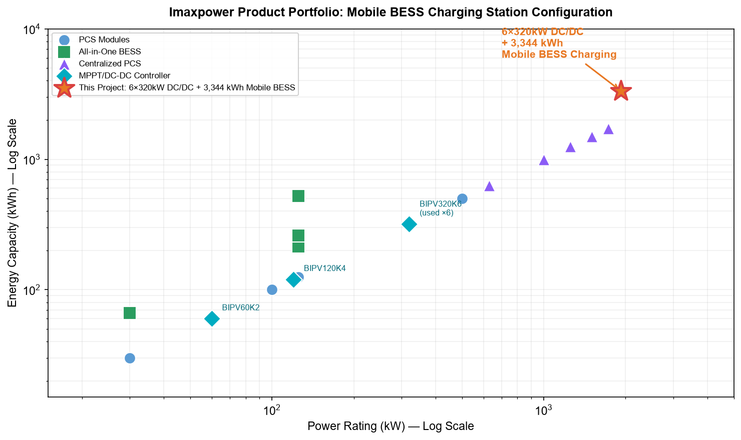
Products are certified to UN38.3, IEC, UL, CE, and RoHS standards, shipping to Europe, North America, Southeast Asia, the Middle East, and Africa without re-engineering. The company offers full customization — from system design and engineering to O&M services — tailored to specific project requirements.
Contact: Coco | Tel/WhatsApp/WeChat: +86-13760212825 | Email: info@imaxpwr.com | www.imax-pwr.com