

How We Designed a 1MW PV-Storage-Charging Microgrid for a Commercial Truck Stop
Engineering Case Study: 1MW Solar PV + 2MWh BESS + 480kW EV Charging Infrastructure
Project Background & Requirements
Our client operates a chain of commercial truck stops along a major highway in the southwestern United States. With the rapid growth of electric commercial trucks, they needed to add EV charging capability while reducing their dependency on grid power, which had high demand charges and frequent outages during peak summer.
Key project requirements:
- 1MW of solar PV generation
- 2MWh BESS energy storage capacity
- Four 120kW DC fast EV charging stations
- Islanding operation capability during grid outages
- Payback period target under 8 years
The site was already developed, so space was limited. We needed to fit all generation, storage and charging infrastructure into the available parking area without disrupting existing operations.
Key Engineering Challenges
Challenge 1: Managing High Peak Loads from Simultaneous EV Charging
When all four DC fast chargers operate at full power, the instantaneous load exceeds 480kW, on top of the existing base load of 200kW for the convenience store and lighting. This creates huge peak demand if directly drawn from the grid, eroding profitability.
Engineering impact: Peak demand charges from the utility could exceed $15,000 per month during summer months, making the business case for EV charging infrastructure economically unviable without a storage-based peak shaving strategy.
Challenge 2: Space Constraints on an Existing Site
Only about 6 acres of available land needed to accommodate solar canopies over parking, battery storage containers, and charging stations. Integrated design was essential to maximize utilization of the available space.
Engineering impact: Traditional separate-component designs would require 30-40% more footprint. We needed an all-in-one or highly integrated approach to meet the spatial constraints.
Challenge 3: Grid Interconnection and Islanding Requirements
The local utility required strict frequency and voltage response, as well as an anti-islanding protection scheme. The system needed to meet all interconnection requirements while still providing the ability to island and keep critical loads running during outages.
Engineering impact: This required a PCS with grid-forming capability and seamless transfer switching (<10ms) to maintain power to critical loads during utility interruptions.
Engineering Analysis
PCS Configuration Logic
The PCS selection was driven by three factors: the site’s peak load profile, the required response speed for peak shaving, and the need for grid-forming capability during islanded operation.
- Rated power: 500kW per PCS unit, two units in parallel for 1MW total capacity
- DC voltage range: 600V–950V, compatible with the 2MWh LFP battery string configuration
- Response speed: <20ms charge-discharge conversion time
- Efficiency: 98.7% maximum conversion efficiency
- Grid-forming capability: Supports VSG mode for inertia and voltage support
Battery Capacity Design
Capacity calculation: Battery Energy (kWh) = Peak Load (kW) × Shaving Duration (h) ÷ System Efficiency
- Peak shaving requirement: 500kW (charging peak reduction)
- Duration: 4 hours (peak demand window)
- System efficiency (PCS + battery): 90%
- Calculated capacity: 500 × 4 ÷ 0.9 ≈ 2,222kWh
- Selected: 2MWh LFP battery system (optimized for cost and footprint)
System Architecture Decision: AC-Coupled vs DC-Coupled
After evaluating different options, we chose an AC-coupled architecture for this project.
Why AC-coupled instead of DC-coupled?
- Existing grid interconnection already in place: AC coupling allowed us to add PV, storage and charging without replacing the existing grid connection
- Flexibility for phased construction: The client could start with PV and storage, then add more charging stations later
- Familiar engineering: AC coupling uses standard switchgear and protection that local contractors are comfortable maintaining
- DC-coupled alternative rejected: While DC coupling offers slightly higher efficiency (2-3%), it would have required replacing the existing 480V AC infrastructure and added complexity to the phased rollout plan
System Architecture
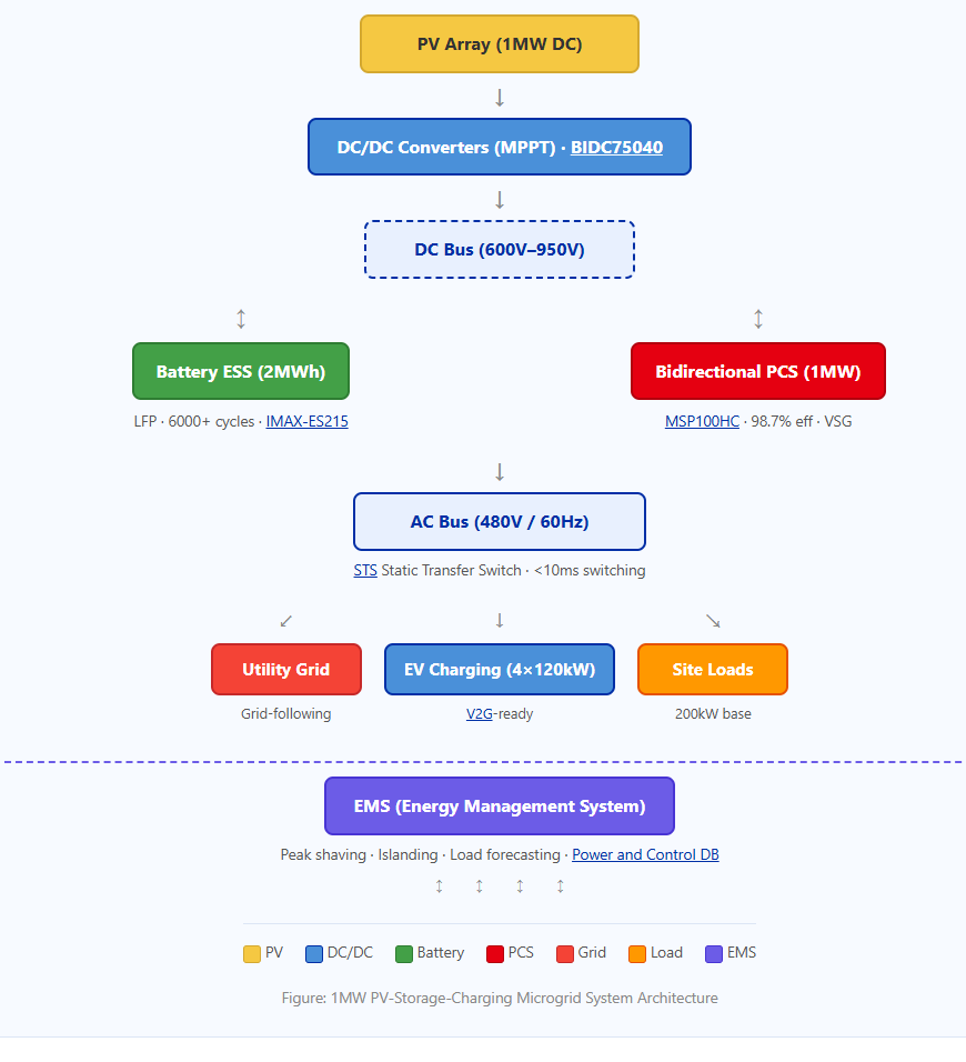
Figure: 1MW PV-Storage-Charging Microgrid System Architecture
IMAXPWR Engineering Solution
Hardware Configuration
- Solar PV: 1MW DC solar array with two 500kW grid-tie inverters
- Energy Storage PCS: Two MSP100HC 100kW modules (total 1MW), 98.7% efficiency, VSG grid-forming capability
- Battery System: 2MWh LFP battery container with integrated BMS, 6000+ cycle life
- DC/DC Converters: IMDC75040 bidirectional isolated modules for MPPT and DC bus regulation
- EMS: Power and Control DB energy management system for peak shaving and islanding coordination
- STS: Static Transfer Switch for seamless <10ms transition between grid-connected and islanding modes
- EV Chargers: Four 120kW DC fast chargers with V2G-ready modules
Control Strategy
- Peak Shaving: BESS discharges during EV charging peaks to reduce demand charges
- PV Self-Consumption: Solar energy stored in BESS during low-load periods for use during peak pricing
- Islanding: Automatic seamless transition to island mode during grid outages, powering critical loads
- Grid-Following + Grid-Forming: PCS operates in grid-following mode during normal operation, switches to grid-forming during islanding
Safety & Reliability Design
- Electrical Protection: Overvoltage, overcurrent, short-circuit, and islanding protection per UL1741 and IEC 62477-1
- Thermal Management: Intelligent forced air cooling with -30°C to +60°C operating range
- Communication: CAN/RS485 interfaces for seamless BMS and EMS integration
- Redundancy: Parallel operation of up to 20 PCS units for N+1 redundancy
Need a Similar Energy Storage System?
Many EPC contractors and project developers face similar challenges when designing BESS and microgrid systems. IMAXPWR engineering team can help evaluate your:
- Power requirements and load profiles
- Energy capacity and backup duration
- System architecture (AC-coupled vs DC-coupled)
- Integration strategy with existing infrastructure
Engineering Comparison
| Parameter | Traditional Diesel Generator Backup | IMAXPWR Microgrid Solution |
|---|---|---|
| Peak Load Management | Not applicable (full generator capacity required) | BESS peak shaving reduces demand charges by 40-60% |
| Fuel/Energy Cost | $0.25–0.35/kWh (diesel) | $0.06–0.08/kWh (solar + storage) |
| Response Time | 10–30 seconds (generator start-up) | <10ms (PCS + STS switching) |
| Emissions | High (CO₂, NOx, particulate) | Zero during solar/storage operation |
| Maintenance | Monthly (oil, filters, cooling) | Quarterly (remote monitoring + periodic checks) |
| Lifetime Cost (10 years) | $2.8–3.2M (fuel + maintenance + replacement) | $1.6–1.9M (CAPEX + OPEX) |
| Grid Independence | Partial (requires fuel supply chain) | Full islanding capability with renewable generation |
Project Performance Evaluation
- System capacity: 1MW PV + 2MWh BESS + 480kW EV charging
- PCS efficiency: 98.7% (peak)
- System availability: 99.5% (projected based on component MTBF)
- Peak demand reduction: 500kW shaved during charging events
- Annual energy cost savings: Estimated $180,000–220,000
- Payback period: 6.5–7.5 years (within 8-year target)
- CO₂ reduction: ~850 metric tons annually compared to grid power
Note: This case study represents an engineering scenario based on IMAXPWR’s energy storage solution experience and industry application requirements. Actual project results may vary based on site conditions and operational patterns.
Key Engineering Lessons Learned
1. Correct PCS sizing requires analyzing the full load profile, not just peak demand
The EV charging load is highly variable. Oversizing the PCS increases CAPEX unnecessarily, while undersizing causes clipping during peak events. We used 15-minute interval load data over 12 months to size the 1MW PCS configuration.
2. AC-coupled architecture provides better flexibility for phased projects
The client wanted the option to add more charging stations in the future. AC coupling allowed us to design a modular system where additional charging capacity can be added without modifying the existing PV or storage infrastructure.
3. Early utility engagement is critical for interconnection approval
We started utility discussions during the conceptual design phase—6 months before submitting the final interconnection application. This identified the need for anti-islanding protection and specific relay settings that we incorporated into the PCS configuration.
4. Thermal management is often underestimated in desert environments
Southwestern US summer temperatures can exceed 45°C. We specified PCS units with -30°C to +60°C operating range and added additional shading for the battery containers to maintain optimal operating temperature.
Common Mistakes to Avoid in Similar Projects
- Incorrect PCS sizing based on average load: Always use peak load with a 1.2–1.3 safety factor for EV charging applications where load is highly variable.
- Poor thermal design for outdoor installations: Battery and PCS performance degrade significantly above 40°C. Specify appropriate cooling and consider site-specific climate data.
- Ignoring utility interconnection requirements: Anti-islanding, frequency ride-through, and power quality requirements vary by utility. Engage early and design PCS controls accordingly.
- Underestimating EMS complexity: Peak shaving, islanding, and PV self-consumption require sophisticated EMS logic. Don’t treat EMS as an afterthought—design it alongside the power hardware.
- No redundancy for critical loads: For sites where power outage is unacceptable, specify N+1 PCS redundancy and ensure STS switching time meets load requirements.
Need Engineering Support for Your Next Project?
Planning a BESS, microgrid or renewable energy project? Send us your project requirements, and our engineering team will provide a customized system recommendation.
Contact Engineer
Request Solution
About The Author
This article was reviewed by Ethan Li, an energy storage system specialist focusing on PCS, bidirectional DC/DC converters and microgrid system design. Ethan has over 15 years of experience in BESS integration, PCS system design, and renewable energy project engineering.
About IMAXPWR
ImaxPWR (Imax Power Technology Co., Ltd.) is a national high-tech enterprise specializing in new energy solutions. As an OEM/ODM manufacturer, IMAXPWR focuses on energy storage power conversion equipment, bidirectional PCS, DC/DC converters, V2G modules, energy storage cabinets and integrated microgrid solutions.
With professional R&D capabilities and power electronics expertise, IMAXPWR provides reliable and customized energy solutions for global customers in industrial and commercial energy storage, renewable energy integration, smart microgrids and charging infrastructure applications.
Our products are certified by CE, UL and ROHS, widely used in smart microgrids, V2G, distributed energy storage and commercial & industrial applications.
FAQ
What is the typical payback period for a PV-storage-charging microgrid?
For commercial applications like this truck stop project, the payback period typically ranges from 6 to 8 years, depending on local electricity rates, demand charges, and available incentives. Our analysis showed a 6.5-7.5 year payback for this 1MW/2MWh system.
How do you determine whether to use AC-coupled or DC-coupled architecture?
AC coupling is preferred for retrofit projects, sites with existing grid interconnection, and phased construction. DC coupling offers 2-3% higher efficiency but requires more complex integration. We chose AC coupling for this project because the client needed flexibility to add more charging stations later.
What PCS features are essential for microgrid applications?
Key features include: grid-forming capability (VSG support) for islanded operation, fast response time (<20ms for charge-discharge conversion), high efficiency (98%+), wide DC voltage range (600-950V), and support for parallel operation (up to 20 units).
Does IMAXPWR support OEM/ODM customization for energy storage systems?
Yes. IMAXPWR provides comprehensive OEM/ODM services for energy storage power conversion equipment, including custom PCS configurations, voltage ranges, power ratings, and enclosure designs to meet specific project requirements.
How do I get started with a microgrid project?
Submit your project parameters including load profile, site location, available space, renewable generation potential, and budget constraints. Our engineering team will provide a preliminary system design and proposal within 24 hours.
Ready to develop your energy storage project?
Contact IMAXPWR technical team for BESS system design, PCS selection, microgrid solutions, and customized energy conversion equipment.
Request Technical Solution
Send Project Requirements
Contact IMAXPWR