

Grid-Forming vs Grid-Following BESS: A Technical Specification Guide for System Integrators
⚡ Engineering comparison of GFM and GFL inverter architectures — selection criteria, weak-grid performance, black-start capability, and project specification insights for BESS integrators.
Introduction: The Engineering Challenge
For system integrators and EPC firms, the choice between a grid‑forming (GFM) and a grid‑following (GFL) battery energy storage system is not about selecting the “more advanced” technology. It is a fundamental architectural decision that determines how the PCS interacts with the grid, what ancillary services it can deliver, and whether the project can meet increasingly stringent grid codes. As inverter‑based resources (IBRs) displace synchronous generation, grids in many regions are becoming weaker — lower short‑circuit ratio (SCR), less inertia, and more volatile frequency dynamics. This guide provides a technical, engineer‑to‑engineer comparison of GFM and GFL BESS architectures, with practical selection criteria for commercial, industrial, and utility‑scale projects.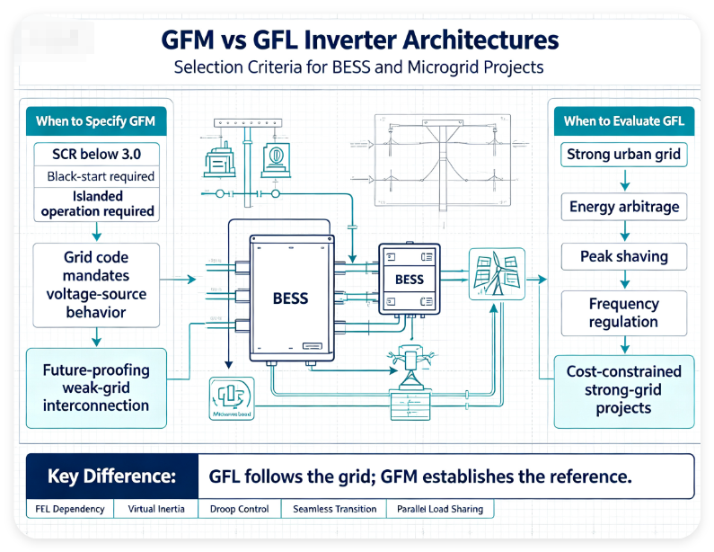
Why This Problem Happens
The distinction between GFM and GFL arises from the fundamental control philosophy of the power conversion system (PCS). A GFL inverter synchronizes to an existing AC voltage and frequency reference — typically using a phase‑locked loop (PLL) — and behaves as a controlled current source. It follows the grid. A GFM inverter, by contrast, maintains an internally generated voltage and frequency reference, behaving as a controlled voltage source that the rest of the system can follow.
This difference becomes critical when the external reference is weak, highly dynamic, or absent. In a strong grid, a GFL BESS works reliably for energy arbitrage, peak shaving, and frequency regulation. But as renewable penetration rises and synchronous inertia declines, the grid reference itself can become unstable during disturbances. A GFL inverter cannot independently energize a dead AC bus — there is no waveform for it to follow. A GFM inverter can establish the grid reference, enabling black‑start and islanded operation.
Technical Factor 1: Voltage‑Source vs Current‑Source Behavior
The PCS in a GFL BESS regulates its output current to meet active and reactive power commands. It relies on the grid to establish voltage. In a GFM BESS, the PCS regulates its output voltage magnitude and frequency, and the grid (or loads) draws current accordingly. This voltage‑source behavior gives GFM converters an inherent stabilizing effect, particularly in weak‑grid areas with low SCR. Studies show that GFM BESS can provide more than 26% better inertia support than GFL devices under transient frequency events.
Technical Factor 2: Grid‑Following Relies on PLL — Grid‑Forming Does Not
GFL inverters typically use a PLL to estimate grid phase angle and frequency. In weak grids with low SCR (below 2.0), PLL performance can degrade, leading to oscillations and instability. GFM inverters do not rely on an external PLL as their fundamental synchronization mechanism. Instead, they use droop control or virtual synchronous generator (VSG) algorithms to set frequency and voltage. This makes GFM inherently more robust in weak‑grid environments.
Engineering Analysis: GFM vs GFL Performance in Key Operating Modes
The table below summarizes the technical differences between GFM and GFL BESS architectures across seven critical engineering dimensions. This is not a marketing comparison — it is a specification reference for integrators evaluating PCS platforms.
| Engineering Dimension | Grid‑Following (GFL) BESS | Grid‑Forming (GFM) BESS |
|---|---|---|
| Control Behavior | Controlled current source | Controlled voltage source |
| Synchronization | PLL‑based, follows external reference | Internal reference, no PLL dependency |
| Weak‑Grid Stability (SCR < 2.0) | Stability challenges; oscillations possible | Robust; superior performance |
| Island Formation | Cannot establish island by itself | Can support island formation |
| Black‑Start Capability | Cannot energize dead AC network | Can provide electrical reference; plant‑level black‑start possible |
| Inertia Support | Limited; relies on reserve controls | Native synthetic / virtual inertia |
| Typical Application | Strong‑grid: arbitrage, peak shaving, regulation | Weak grids, microgrids, black‑start, grid‑code compliance |
Design Considerations for System Integrators
When specifying a BESS PCS for a project, integrators should evaluate the following technical parameters:
- Point of Common Coupling (PCC) Strength: Measure the short‑circuit ratio (SCR) at the interconnection point. If SCR is below 3.0, GFM should be strongly considered.
- Grid‑Code Requirements: Many system operators (AEMO, MISO, ERCOT, UK NESO) are proposing or mandating GFM capability for new utility‑scale BESS. Check the specific requirements for your project region.
- Operating Modes Required: Does the project require black‑start, islanded operation, or seamless transition between grid‑connected and island modes? These are GFM features.
- Hardware vs Firmware: The same hardware can often switch between GFL and GFM modes via firmware. Evaluate whether the PCS supplier offers field‑upgradable GFM capability.
- Parallel Operation: For multi‑MW systems with parallel GFM inverters, verify that the control system supports droop or VSG‑based load sharing without oscillation.
⚙️ If you are designing a BESS, microgrid or renewable energy system, IMAXPWR engineering team can help evaluate your technical requirements and provide a customized solution.
Recommended Engineering Approach
For most new utility‑scale projects (10 MW and above), GFM is rapidly becoming the procurement standard. For commercial and industrial (C&I) projects connected to strong urban grids, GFL may still be the most cost‑effective choice. However, if the project scope includes any of the following, specify GFM:
- Connection to a weak grid (SCR < 3.0)
- Black‑start or islanded operation requirement
- Grid code that mandates synthetic inertia or voltage‑source behavior
- Microgrid or remote off‑grid application
- Future‑proofing for evolving grid‑code requirements
Common Mistakes to Avoid
- Assuming GFM = Black‑Start: GFM control can provide the electrical reference, but plant‑level black‑start requires additional systems (battery auxiliaries, protection coordination).
- Ignoring SCR in Site Assessment: Many projects specify GFM without measuring SCR, or specify GFL for a site with SCR below 2.0, leading to performance issues and oscillations.
- Overlooking Firmware Upgrade Path: Some PCS platforms support GFM via firmware upgrade. Specify this in procurement to avoid costly hardware replacement later.
- Treating GFM as a Binary Choice: The same hardware can switch between modes. The question is not “GFM or GFL” but “under what operating conditions does each mode apply?”
FAQ
What is the difference between grid‑forming and grid‑following BESS?
A grid‑following BESS synchronizes to an existing grid voltage and frequency reference (current‑source behavior). A grid‑forming BESS maintains its own internal voltage and frequency reference (voltage‑source behavior) and can establish the grid.
When should I specify a grid‑forming PCS for my BESS project?
Specify GFM for weak‑grid connections (SCR < 3.0), projects requiring black‑start or islanded operation, microgrids, and regions where grid codes mandate synthetic inertia or voltage‑source behavior.
Does grid‑forming automatically mean black‑start capability?
No. GFM control can provide the electrical reference, but plant‑level black‑start requires additional systems including battery auxiliaries, protection coordination, and sequence control.
What is virtual synchronous generator (VSG) in grid‑forming BESS?
VSG is a GFM control algorithm that emulates the inertial response of a synchronous generator, providing synthetic inertia to support frequency stability in low‑inertia power systems.
Can the same PCS hardware operate in both grid‑following and grid‑forming modes?
Yes. Many modern PCS platforms support both modes via firmware configuration, allowing the same hardware to switch roles depending on operating conditions.
About IMAXPWR
ImaxPWR (Imax Power Technology Co., Ltd.) is a national high‑tech enterprise specializing in new energy solutions. As an OEM/ODM manufacturer, IMAXPWR focuses on energy storage power conversion equipment, bidirectional PCS, DC/DC converters, V2G modules, energy storage cabinets and integrated microgrid solutions. With strong R&D capabilities and power electronics expertise, IMAXPWR provides reliable energy conversion solutions for global customers in industrial and commercial energy storage, renewable energy integration and smart microgrid applications.
🔋 Need help specifying the right PCS architecture for your project?
Contact IMAXPWR engineering team for technical evaluation, customized solutions, and project‑specific PCS recommendations.
📋 Request Technical Solution
📎 Send Project Requirements