

Abstract
The bidirectional DC-DC converter sits between the battery stack and the DC link in a battery energy storage system (BESS), and its topology choice directly determines system efficiency, cost, footprint, and reliability. According to the International Energy Agency, global battery storage deployment reached 108 GW in 2025, a 40% year-over-year increase, with LFP chemistry accounting for roughly 90% of installations. As battery voltage ratings climb from 800 Vdc toward 1500 Vdc, engineers must choose between non-isolated buck-boost, dual active bridge (DAB), LLC resonant, and CLLC topologies. This article compares the four major bidirectional DC-DC converter architectures on efficiency, ZVS range, component count, control complexity, and cost, then walks through control strategy design and a practical 1500 Vdc selection framework for grid-scale and C&I storage projects.
1. Technical Background: Why the DC-DC Stage Matters in BESS
In a modern DC-coupled BESS, the battery stack voltage varies widely with state of charge (SOC): a 600 Vdc nominal LFP string might swing from 450 Vdc near empty to 750 Vdc near full, while a 1500 Vdc system spans roughly 1000 Vdc to 1500 Vdc. The DC link, however, must stay at a fixed voltage so the grid-tied PCS can operate at its optimal efficiency point. The bidirectional DC-DC converter is the stage that bridges this gap: it steps battery voltage up to the DC link during discharge, and steps it down during charging, while supporting power flow in both directions.
Without a DC-DC stage, the PCS must tolerate the full battery voltage swing on its DC input, which narrows its efficient operating window and forces a higher-rated (more expensive) PCS. With a properly selected DC-DC converter, the PCS sees a stable DC link and the battery can be sized independently of the grid interface voltage. This is why DC-coupled architectures have become the dominant design for utility-scale and C&I storage projects, according to IEA analysis.
2. Problem Analysis: Common Topology Misconceptions
2.1 “Isolated always means better”
A frequent engineering assumption is that galvanic isolation is mandatory for safety. In practice, IEC 62477-1:2022 permits non-isolated bidirectional converters within a SELV or reinforced-insulation architecture when the system maintains proper clearance and creepage distances. Non-isolated buck-boost topologies achieve peak efficiencies above 99% because they avoid the high-frequency transformer loss. The trade-off is that the battery and DC link share a common ground, which limits the ability to float the battery stack and complicates modular series-parallel configurations.
2.2 “DAB is the default isolated choice”
The dual active bridge (DAB) is widely deployed because of its simple structure and single-phase-shift control, but its ZVS (zero-voltage switching) range narrows at light load and at voltage ratios far from unity. In BESS applications where the battery voltage swings 2:1 or more, a plain DAB suffers efficiency penalties at low SOC. Resonant variants such as CLLC and series-resonant DAB (SR-DAB) address this gap, but add design complexity and component count.
2.3 Weak-grid and high-temperature constraints in emerging markets
For projects in Southeast Asia, the Middle East, Africa, and Latin America — where weak grids, frequent voltage sags, and ambient temperatures above 45 °C are common — the DC-DC converter must maintain tight DC-link regulation during grid disturbances and derate gracefully at high temperature. Selection based solely on datasheet peak efficiency at 25 °C ignores these real-world operating envelopes.
3. Design Logic: Four Major Bidirectional DC-DC Topologies Compared
The following table compares the four topologies most commonly specified for BESS applications. Each topology is evaluated on seven engineering dimensions that directly affect project-level decisions.
| Dimension | Non-Isolated Buck-Boost | DAB (Dual Active Bridge) | LLC / CLLC Resonant |
|---|---|---|---|
| Isolation | No | Yes (HF transformer) | Yes (HF transformer + resonant tank) |
| Peak Efficiency | ≥99.2% | 97.5–98.5% | 98–99% |
| ZVS Range | Full range (synchronous rectification) | Narrow at light load / off-ratio | Wide (near full load range) |
| Component Count | Lowest (4 switches, 1 inductor) | 8 switches + HF transformer | 8 switches + transformer + resonant tank |
| Voltage Range Flexibility | Wide (buck & boost modes) | Wide (phase-shift adjusts gain) | Narrow (frequency modulation; best near resonance) |
| Control Complexity | Low (simple PI loop) | Medium (SPS / DPS / EPS modulation) | High (frequency tracking + resonant control) |
| Relative Cost | Lowest | Medium | Highest |
| Typical BESS Use Case | Battery & DC link same voltage family; cost-sensitive C&I | Modular stacked BESS; 750–1500 Vdc links | High-efficiency utility-scale; narrow battery voltage band |
3.1 Non-Isolated Bidirectional Buck-Boost
The non-isolated topology uses a four-switch buck-boost (or synchronous buck/boost pair) with a single inductor. It achieves the highest efficiency because no high-frequency transformer contributes loss, and it naturally supports both step-up and step-down operation. ImaxPWR’s BIDC series, for example, uses an intelligent bidirectional buck-boost architecture rated at up to 250 kW with peak efficiency above 99.2% and power dynamic response under 5 ms. The limitation is the shared ground: the battery stack cannot be isolated from the DC link, which matters if the battery is referenced to a different protection class than the PCS.
3.2 Dual Active Bridge (DAB)
The DAB uses two full bridges linked by a high-frequency transformer. Single-phase-shift (SPS) control adjusts the phase angle between the bridges to regulate power flow. It provides galvanic isolation and moderate cost, but ZVS is lost at light load and when the voltage ratio deviates from the transformer turns ratio. Extended-phase-shift (EPS) and dual-phase-shift (DPS) modulation extend the ZVS range but add control complexity. For BESS applications with wide battery voltage variation, DAB remains a practical choice when isolation is required and the voltage range is managed by parallel module configurations.
3.3 LLC and CLLC Resonant Converters
The bidirectional CLLC resonant converter adds a resonant tank (inductor-capacitor-inductor-capacitor) between the bridges and transformer. The resonant network enables ZVS across a wide load range in both directions, making it the most efficient isolated topology for high-power, continuous-duty BESS applications. The trade-off is narrower operating voltage range: the switching frequency must vary to regulate output voltage, and at voltage ratios far from the resonant point the efficiency drops. Per EDN Power Tips analysis, CLLC achieves near-full-range ZVS but requires careful resonant tank design.
4. Control Strategy: How the DC-DC Converter Manages BESS Power
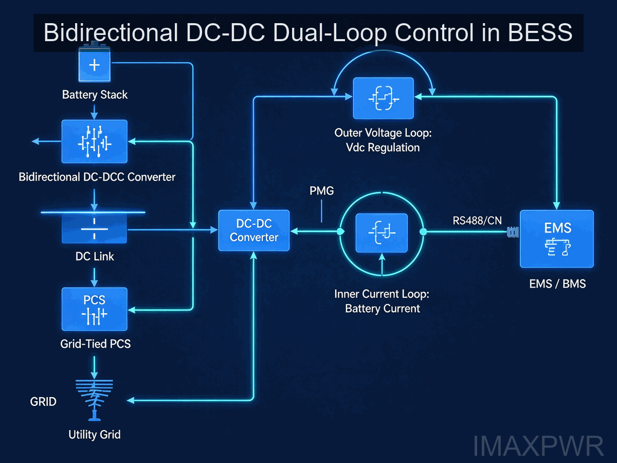
Regardless of topology, the control loop for a BESS bidirectional DC-DC converter uses a cascaded dual-loop structure. The outer voltage loop maintains the DC-link voltage at its setpoint (typically 750 Vdc or 1500 Vdc), and the inner current loop regulates the battery-side current to track the reference generated by the outer loop or the EMS. This structure provides fast dynamic response and protects the battery from overcurrent.
4.1 Charging and Discharging Mode Switching
During charging, the converter operates in buck mode: the DC link supplies power to the battery, and the current loop regulates battery current according to the EMS command (CC or CV mode). When SOC reaches the upper threshold (typically 90–95% for LFP), the controller transitions from constant-current (CC) to constant-voltage (CV) taper charge. During discharge, the converter enters boost mode: the battery supplies the DC link, and the voltage loop maintains DC-link regulation. The transition between modes must be seamless to avoid DC-link voltage transients that could trigger PCS overvoltage trips.
4.2 Parallel Operation and Current Sharing
Utility-scale BESS deployments stack multiple DC-DC modules in parallel to reach megawatt-scale power. ImaxPWR’s BIDC250 supports up to 40 parallel units with current imbalance below 7%, using active current sharing over CAN or Modbus. Proper parallel operation requires droop control or master-slave arbitration, and the EMS must coordinate the charging current reference so no single module exceeds its thermal limit during long-duration discharge cycles.
5. Common Engineering Errors and Optimization
Error 1: Sizing the DC-DC for peak efficiency at one operating point
Datasheet peak efficiency is measured at nominal voltage and 50–75% load. In real BESS operation, the converter spends most of its time at 20–80% load and at battery voltages that swing with SOC. Specify the efficiency curve across the full operating envelope, not just the peak point. Ask the manufacturer for efficiency data at 20%, 50%, and 100% load across the battery voltage range.
Error 2: Ignoring thermal derating in high-temperature markets
Most converters derate linearly above 40 °C ambient. A 250 kW module rated at 50 °C may deliver only 200 kW continuously. For projects in the Middle East, North Africa, or Southeast Asia where cabinet interior temperatures exceed 50 °C, specify liquid cooling or derate the installed capacity from the start.
Error 3: Overlooking communication protocol compatibility
The DC-DC converter must share its voltage, current, and SOC data with the BMS and EMS over a common protocol. ImaxPWR modules support RS485 Modbus RTU, CAN, and Ethernet Modbus TCP. Confirm that the EMS/BMS in your project speaks the same protocol before ordering; missing protocol converters delay commissioning by weeks.
6. Selection Guide for 1500 Vdc BESS Applications
The industry trend toward 1500 Vdc battery strings is driven by cabling cost reduction and PCS efficiency gains. At 1500 Vdc, the same power level flows at lower current, cutting cable cross-section by roughly half compared to 750 Vdc systems. The following selection framework maps typical BESS architectures to recommended DC-DC topologies and power ratings.
| System Architecture | Battery Voltage Range | Recommended Topology | Typical Module Rating |
|---|---|---|---|
| C&I storage (200–1000 kWh) | 150–1000 Vdc | Non-isolated buck-boost | 20–125 kW |
| Utility-scale DC-coupled | 1000–1500 Vdc | DAB or CLLC (isolated) | 125–500 kW |
| PV + storage hybrid | 200–1500 Vdc (PV + battery) | MPPT buck-boost (non-isolated) | 50–250 kW |
| Mobile / charging V2G | 200–750 Vdc | High-freq isolated DAB | 15–40 kW |
ImaxPWR’s BIDC1500100 (125 kW, 1500 Vdc) and BIDC1000250 (250 kW, 150–1000 Vdc) cover the C&I and mid-scale utility range. Both modules comply with IEC 62477-1:2012 safety requirements for power electronic converter systems up to 1500 Vdc, and carry UL1741 and CE certification. For battery-side safety coordination, the BMS should comply with IEC 62619:2022 for lithium cells and batteries in industrial applications.
7. Industry Trends
According to the IEA, 108 GW of new battery storage was deployed worldwide in 2025, and installed capacity is now eleven times higher than in 2021. LFP chemistry accounts for roughly 90% of new deployments. As the market scales, three trends shape DC-DC converter selection:
- Higher DC-link voltage: 1500 Vdc is becoming the standard for utility-scale systems, with 2000 Vdc emerging in pilot projects. Lower current means thinner cables and smaller switchgear.
- Modular power blocks: 125 kW and 250 kW power blocks are replacing custom-engineered skids, reducing lead time and enabling parallel scaling from 100 kW to 100 MW.
- SiC and GaN adoption: Silicon carbide MOSFETs enable higher switching frequency, shrinking magnetics and improving light-load efficiency. Expect the cost premium for SiC designs to continue narrowing.
8. Author’s Perspective
After working on BESS projects across Southeast Asia, the Middle East, and Africa, my practical take is that topology selection is rarely the dominant risk in a project. Most field issues come from mismatched voltage ranges, underestimated thermal derating, or protocol integration gaps rather than a flawed topology. Start by defining the battery voltage window, the DC-link target, and the ambient temperature range, then choose the topology that meets those constraints at the lowest cost per kW.
For C&I projects below 1 MWh, a non-isolated buck-boost module with a wide input range (such as 150–1000 Vdc) is almost always the right answer: it delivers above 99% efficiency at the lowest cost, and the shared ground is acceptable because the battery and PCS are housed in the same cabinet. For utility-scale projects where battery strings are stacked and galvanic isolation is required between sections, an isolated DAB or CLLC module is justified by modularity and serviceability. Do not over-specify CLLC for a project where a DAB would meet the same isolation and efficiency requirements at lower cost.
Finally, always ask the manufacturer for efficiency curves across the full load and voltage envelope, not just the peak point. The 1–2% difference in average efficiency over a 10-year operation life dwarfs the upfront cost difference between topologies.
9. Frequently Asked Questions
Q1: What is the difference between isolated and non-isolated bidirectional DC-DC converters in a BESS?
An isolated converter uses a high-frequency transformer to provide galvanic separation between the battery side and the DC link, while a non-isolated converter shares a common ground through a buck-boost inductor. Isolated designs (DAB, CLLC) support stacked battery configurations and safety segregation; non-isolated buck-boost designs achieve higher efficiency (above 99%) at lower cost but tie the battery and DC link to the same reference.
Q2: Which topology is most efficient for a 1500 Vdc utility-scale BESS?
The CLLC resonant converter typically achieves the highest peak efficiency (98–99%) among isolated topologies due to near-full-range ZVS. For non-isolated designs, the bidirectional buck-boost reaches above 99.2% because it eliminates transformer loss. The optimal choice depends on whether galvanic isolation is required: for isolated 1500 Vdc systems, CLLC or DAB are standard; for non-isolated same-voltage-family architectures, buck-boost is the most efficient.
Q3: How does a bidirectional DC-DC converter control battery charging and discharging?
A cascaded dual-loop control is standard: the outer voltage loop maintains the DC-link voltage setpoint, and the inner current loop regulates battery-side current. During charging (buck mode), the current loop enforces CC/CV charging profiles; during discharging (boost mode), the voltage loop stabilizes the DC link while the EMS commands the discharge current. Mode transitions are designed to be seamless to avoid DC-link transients.
Q4: What safety standards apply to DC-DC converters in BESS applications?
The primary standard is IEC 62477-1:2022 (Safety requirements for power electronic converter systems and equipment, up to 1500 Vdc). For battery packs, IEC 62619:2022 applies to secondary lithium cells. North American deployments additionally require UL1741 certification. EMC compliance follows IEC 61000 series. Always verify that the converter and the battery system together meet the applicable standards, not just the individual components.
Q5: Why is 1500 Vdc becoming the dominant bus voltage for grid-scale storage?
Higher DC voltage reduces current for the same power, cutting cable cross-section, switchgear rating, and resistive losses. At 1500 Vdc versus 750 Vdc, cable sizing is roughly halved. The IEC 62477-1 standard covers systems up to 1500 Vdc, which is why utility-scale DC-coupled projects standardize on 1000–1500 Vdc battery strings.
Q6: How many DC-DC modules can be paralleled in one BESS cabinet?
It depends on the module design and current-sharing capability. ImaxPWR’s 250 kW BIDC module supports up to 40 parallel units with imbalance below 7%, using CAN or Modbus active current sharing. Most vendors rate parallel capability between 8 and 40 units. Always confirm the maximum parallel count and the current imbalance specification, as uneven sharing accelerates thermal aging on overloaded modules.
Q7: What efficiency should I expect from a bidirectional DC-DC converter at partial load?
Peak efficiency (at 50–75% load, nominal voltage) ranges from 97.5% for DAB to above 99.2% for non-isolated buck-boost. At 20% load, expect a 1–2 percentage point drop depending on topology. Ask the manufacturer for the efficiency curve across 20–100% load and the full battery voltage range, not just the peak efficiency number, because BESS systems spend most operating hours at partial load.
Related Reading: Bidirectional DC-DC Converter in Energy Storage: Application and Working Principle · What is a Power Conversion System (PCS)? · 125kW 1500Vdc Bidirectional DC-DC Converter BIDC1500100 · 250kW Bidirectional DC-DC Converter BIDC1000250 · DC-DC Converter Product Catalog
About the Author
Ethan Li, energy storage systems engineer at ImaxPWR Power Co., Ltd., with years of experience in PCS, DC/DC converters, BESS, and microgrid design. He has participated in multiple domestic and international energy storage projects in solution design and technical support.
ImaxPWR is a National High-Tech Enterprise and a source manufacturer of integrated energy storage products and system solutions. This article was reviewed by Ethan Li.
About ImaxPWR
ImaxPWR Power Co., Ltd. (Brand: ImaxPWR) is a National High-Tech Enterprise and source manufacturer, covering bidirectional converters, DC/DC, energy management, and energy storage cabinet integration, providing design, delivery, and O&M services. Products are CE, UL, and IEC certified, with power blocks from 3 kW to 500 kW serving C&I and utility-scale storage projects across Southeast Asia, the Middle East, Africa, and Latin America.
Need the full technical documentation or a tailored design?
Contact us to discuss your BESS architecture, battery voltage window, and DC-DC topology selection. Our engineering team provides system-level design support from 100 kW to multi-megawatt storage projects.
Contact: COCO
Tel / WhatsApp: +86-13760212825
Email: info@imaxpwr.com
Website: https://imax-pwr.com
© 2026 ImaxPWR Power Co., Ltd. · This article is for technical education purposes. Data sourced from industry public materials, international standards, and engineering practice.