

Abstract
A common DC bus architecture keeps photovoltaic (PV) generation, battery storage, and DC loads on a shared high-voltage DC rail, eliminating one AC-DC conversion stage compared with AC-coupled systems. Field measurements and industry analyses consistently show 5–12% higher solar-to-battery charging efficiency and 2–7 percentage points higher round-trip efficiency for DC-coupled topologies. This article breaks down four practical common DC bus energy storage scenarios—single PV+ESS, PV-storage-charging, multi-rack ESS with string DC/DC, and full DC microgrids—explains the control logic and trade-offs of each, and gives engineers a decision framework for selecting the right topology based on project scale, existing infrastructure, and load profile.
1. Technical Background: Why a Common DC Bus Matters
In a conventional AC-coupled PV-storage system, solar DC power is inverted to AC at the PV inverter, then rectified back to DC at the battery PCS for charging, and inverted again to AC when discharging. Each conversion stage dissipates 2–4% of energy as heat. A common DC bus architecture collapses this chain: PV connects through an MPPT DC/DC converter, the battery through a bidirectional DC/DC converter, and both share a single DC rail. Only one bidirectional PCS interfaces the DC bus to the AC grid.
According to a 2026 comparative analysis by SAJ Electric, DC-coupled systems achieve 95–98% round-trip efficiency when charging from solar, versus 90–94% for AC-coupled systems. Over a 20-year project life with daily cycling, that 4–7% gap translates to meaningful additional usable energy and a faster payback period. SAJ Electric: AC-Coupled vs DC-Coupled Systems (2026)
The global microgrid market reached USD 28.9 billion in 2025 and is projected to grow at an 18.3% CAGR through 2035, with DC microgrids capturing an increasing share due to their efficiency and compatibility with DC-native loads like EV chargers and data center equipment. Global Market Insights: Microgrid Market Report (2026)
2. Problem Analysis: When AC Coupling Falls Short
AC coupling remains dominant for retrofits and large utility-scale systems because it allows independent expansion of PV and storage. But it introduces three engineering problems that a common DC bus solves directly:
- Conversion chain losses: PV→AC→DC (battery charge)→AC (discharge) creates three conversion stages. A common DC bus reduces this to one DC-AC conversion at the PCS.
- Reverse power and curtailment complexity: In AC-coupled systems with export limits, the PV inverter and storage PCS must coordinate through external controllers to prevent reverse power. On a DC bus, the EMS controls power flow at a single point—the PCS grid interface.
- DC load mismatch: EV fast chargers, data center IT loads, and LED lighting are inherently DC. Powering them from an AC bus requires additional AC-DC conversion inside each load. A common DC bus can feed these loads directly.
In weak-grid regions across Southeast Asia, Africa, and Latin America, voltage fluctuations and frequency instability further degrade AC-coupled system performance. A DC bus provides a stable voltage reference that is decoupled from grid disturbances, making the PCS the sole point of grid synchronization. Per IEC 62548-1:2023, PV array DC wiring and protection must be designed for the maximum system voltage, which on a common DC bus typically ranges from 600–1500 Vdc.
3. Four Common DC Bus Scenarios
3.1 Scenario 1: Single PV + ESS Common DC Bus (Centralized PCS)
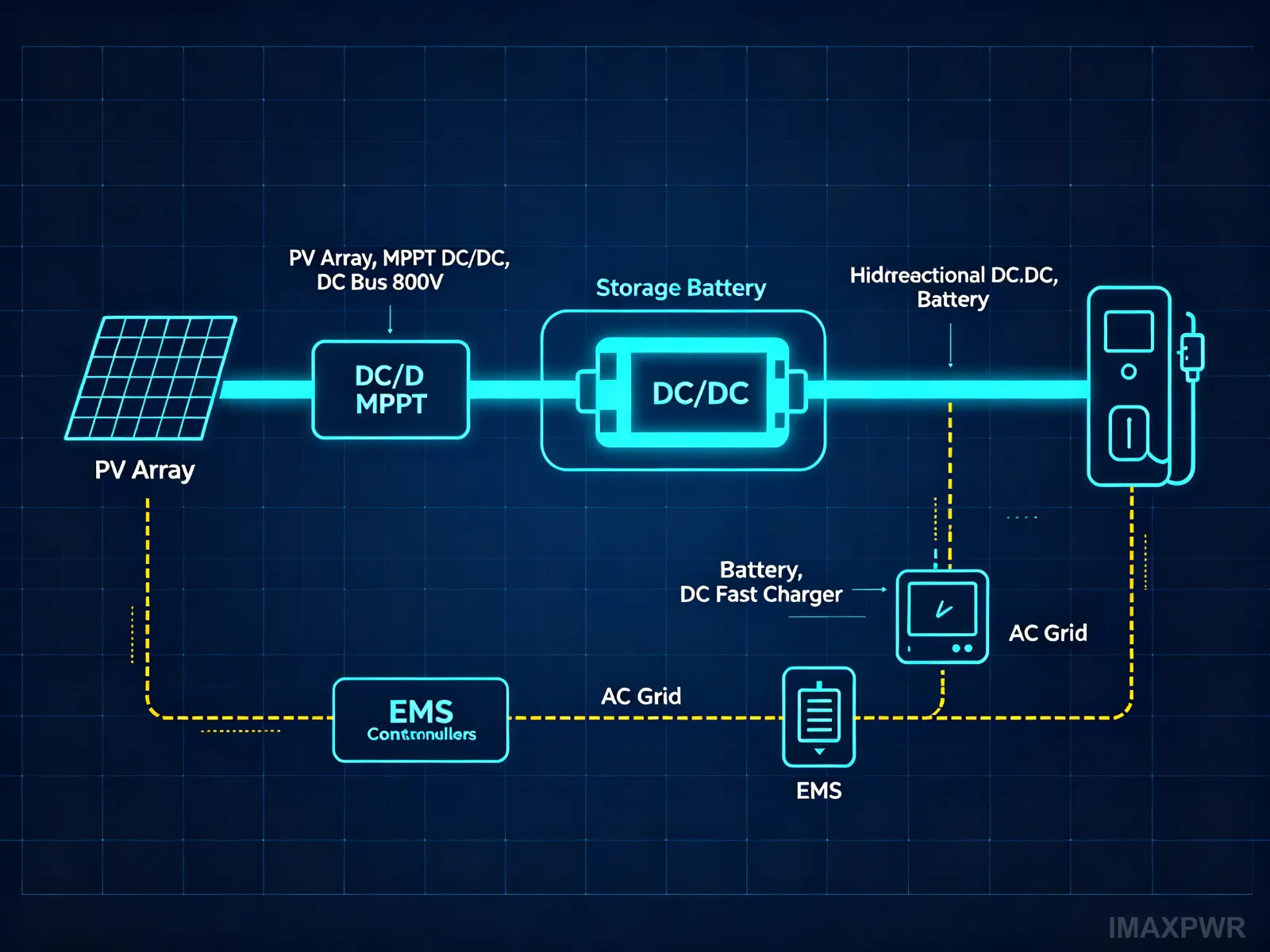
Topology: PV array → MPPT DC/DC converter → common DC bus ← bidirectional DC/DC ← battery bank. The DC bus connects to a single centralized bidirectional PCS that interfaces with the AC grid and local loads. The EMS coordinates MPPT tracking, battery charging/discharging, and PCS power setpoints.
Control logic: When PV generation exceeds load demand, surplus DC power flows through the bus to charge the battery via the bidirectional DC/DC. If the battery is full and export is restricted, the EMS curtails PV by reducing MPPT output. When PV is insufficient, the battery discharges through the same DC/DC to supply the DC bus, and the PCS inverts to AC for loads. The grid serves as backup when both PV and battery are depleted.
Key advantages: Only one PCS is needed, reducing equipment cost and footprint. The single conversion stage gives the highest solar-to-battery efficiency (95–97%). Control is straightforward because all power flow is managed at the DC bus level.
Limitations: Scaling is constrained by the PCS capacity. Adding more PV or storage later may require upgrading the PCS. The architecture is best suited for new installations where the PV and storage are designed together from the start.
Best for: New residential and small commercial PV-storage systems (10–500 kW), off-grid power systems, and projects where PV and storage capacities are co-designed.
3.2 Scenario 2: PV-Storage-Charging Common DC Bus (DC Fast Charger Direct)
Topology: PV → MPPT DC/DC → common DC bus; battery → bidirectional DC/DC → common DC bus; DC fast chargers connect directly to the DC bus without an intermediate AC-DC stage. A bidirectional PCS connects the DC bus to the AC grid for supplementary power and export.
Control logic: The EMS prioritizes PV power for charging vehicles. When PV output exceeds charging demand, surplus energy charges the battery. When vehicle demand exceeds PV + battery capacity, the PCS draws supplementary power from the grid. During low-demand periods, the battery charges from PV or off-peak grid power. The direct DC connection eliminates the charger’s internal AC-DC conversion, improving overall station efficiency by an estimated 3–5%.
According to ImaxPWR’s internal system analysis, a PV-storage-charging station on a common DC bus can achieve station-level efficiencies of 92–95%, compared with 87–90% for an AC-bus architecture where each charger performs its own AC-DC conversion. The DC bus voltage is typically maintained at 600–1000 Vdc to match both EV battery voltages and PV string voltages.
Key advantages: Highest efficiency for charging applications. Reduced equipment count (no individual AC-DC modules in each charger). Enables peak shaving at the grid connection point, reducing demand charges. Supports V2G (vehicle-to-grid) when bidirectional DC/DC modules are used on the charger side.
Limitations: DC bus voltage must be carefully managed to match both PV maximum power voltage and EV battery voltage range. High-power charging (≥120 kW per stall) requires robust DC bus design with adequate cable sizing and protection.
Best for: Highway service area charging stations, bus depots, commercial fleet charging, and campus PV-storage-charging integrated stations. The ImaxPWR IMDC100040 40kW DC charging module with 250–825 Vdc input is well-suited for this architecture.
3.3 Scenario 3: Multi-Rack ESS Common DC Bus (String DC/DC)
Topology: Multiple battery racks, each with its own bidirectional DC/DC converter, connect in parallel to a common DC bus. A centralized PCS (or parallel PCS modules) interfaces the DC bus to the grid. PV may also connect through MPPT DC/DC converters on the same bus.
Control logic: Each rack-level DC/DC converter independently manages its battery’s state of charge (SOC), voltage, and current. This “string” architecture eliminates circulating currents between racks with different SOCs, internal resistances, or aging levels. The EMS dispatches power setpoints to each DC/DC based on available capacity, ensuring balanced utilization. The centralized PCS handles grid-tied inversion and grid support functions.
Without per-rack DC/DC converters, paralleling battery racks directly on a DC bus causes circulating currents and the “barrel effect”—the system’s usable capacity is limited by the weakest rack. Per-rack DC/DC conversion solves this by providing galvanic isolation (when using high-frequency isolated topologies) and independent voltage regulation.
The ImaxPWR bidirectional high-frequency isolated DC/DC modules (5–20 kW, 600–850 Vdc bus, 200–750 Vdc battery side, up to 97% efficiency) are specifically designed for this application. Each module can be assigned to one battery rack, supporting up to 60 modules in parallel for large-scale systems.
Key advantages: Rack-level SOC management eliminates circulating currents. Supports mixing of new and used battery racks, different capacities, and different chemistries. Maximizes usable capacity per rack. Modular expansion—add racks and DC/DC modules without changing the PCS.
Limitations: Higher initial cost due to per-rack DC/DC converters. Additional conversion stage (battery→DC/DC→bus→PCS) slightly reduces round-trip efficiency compared with Scenario 1, though the capacity utilization gain typically offsets this over the project lifetime.
Best for: Commercial and industrial energy storage (200 kWh–5 MWh), battery second-life / echelon utilization projects, and systems where battery rack consistency cannot be guaranteed.
3.4 Scenario 4: DC Microgrid (Multi-Source, Multi-Load)
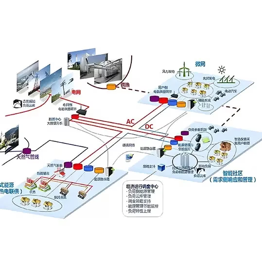
Topology: A high-voltage DC bus (typically 750 Vdc, ±375 Vdc, or 1500 Vdc) serves as the backbone connecting multiple energy sources and loads: PV via MPPT DC/DC, battery storage via bidirectional DC/DC, wind via rectifier, diesel generator via AC-DC rectifier (optional), DC loads (data centers, LED lighting, DC motors) connected directly, and AC loads via the PCS. The microgrid EMS manages all sources and loads, supporting both grid-tied and islanded operation.
Control logic: The EMS implements hierarchical control: primary control (local droop control at each converter for fast voltage/current regulation), secondary control (bus voltage restoration and SOC balancing), and tertiary control (economic dispatch, peak shaving, demand response). In grid-tied mode, the PCS regulates DC bus voltage. In islanded mode, the battery DC/DC takes over bus voltage regulation, and the PCS operates as a grid-forming inverter for AC loads.
Per IEC 62933-1:2024 and IEC 62933-5-1:2024, grid-integrated energy storage systems must comply with safety requirements for battery management, overcurrent protection, and isolation monitoring. In a DC microgrid, these protections are implemented at each converter interface and at the DC bus level (DC circuit breakers or fuses).
Key advantages: Highest system-level efficiency due to direct DC supply of DC-native loads. Multi-source redundancy improves reliability. Black-start capability—the battery and PV can establish the DC bus without grid power. Seamless grid-tied/islanded transition. Supports future addition of new DC sources and loads without reconfiguring the AC side.
Limitations: Highest system complexity and cost. Requires a sophisticated EMS with real-time optimization. DC protection (fault current interruption) is more challenging than AC due to the absence of zero-crossing. Standardization of DC microgrid voltages and interoperability is still evolving.
Best for: Zero-carbon campuses, data centers with DC power distribution, island and remote community microgrids, military bases, and industrial parks with high DC load penetration. The global DC microgrid market is projected to exceed USD 51.8 billion by 2035, growing at over 19% CAGR. Research Nester: DC Microgrid Market Forecast (2026)
4. Common Engineering Errors and Optimization
Error 1: Undersized DC Bus Cabling
The DC bus carries the sum of all source and load currents. At 800 Vdc and 500 kW, bus current exceeds 625 A. Undersized cabling causes voltage drops, excessive heating, and fire risk. Optimization: Size DC bus conductors for maximum continuous current × 1.25 safety factor, with voltage drop limited to ≤2% of nominal bus voltage. Use parallel busbars for high-current applications.
Error 2: Ignoring DC Arc Flash Hazards
DC arcs do not self-extinguish at zero-crossing like AC arcs. A fault on a 1500 Vdc bus can sustain a dangerous arc flash. Optimization: Install DC-rated circuit breakers or fuses with adequate interrupting capacity. Implement arc fault detection devices (AFDDs). Maintain proper working distances per NFPA 70E or local equivalent.
Error 3: Mismatched Voltage Ranges Between PV and Battery
PV string maximum voltage (at low temperature) must not exceed the DC/DC converter’s input rating, and the battery’s full charge voltage must be within the bidirectional DC/DC’s output range. Optimization: Select DC/DC converters with wide input/output ranges. The ImaxPWR BIDC75040 supports 600–850 Vdc bus and 200–750 Vdc battery, providing ample margin for typical LFP battery systems.
Error 4: Single-Point-of-Failure EMS
If the EMS crashes, all converters may default to unsafe states. Optimization: Implement local fallback control at each converter (droop control, voltage-limited charging). Use redundant EMS hardware with hot standby. Ensure converters can operate in a degraded “safe mode” without communication.
5. Selection Guide: Which Scenario Fits Your Project?
| Dimension | S1: PV+ESS | S2: PV-Storage-Charging | S3: Multi-Rack ESS | S4: DC Microgrid |
|---|---|---|---|---|
| Typical Power Range | 10–500 kW | 120 kW–2 MW | 200 kW–5 MW | 500 kW–20+ MW |
| Round-Trip Efficiency | 95–97% | 92–95% | 90–93% | 88–92% |
| System Complexity | Low | Medium | Medium-High | High |
| Relative Cost | Low | Medium | Medium-High | High |
| Scalability | Limited (PCS) | Good | Excellent | Excellent |
| Off-Grid Capability | Yes | Yes | Yes | Best (black-start) |
| Key ImaxPWR Products | Hybrid PCS, MPPT DC/DC | IMDC100040, BIDC75040, PCS | BIDC75040 (per rack), MSP100HC PCS | Full product range + EMS |
Decision rule of thumb: If you are designing a new system with co-located PV and storage under 500 kW, start with Scenario 1. If EV charging is a core load, Scenario 2 gives the best efficiency. If you have multiple battery racks—especially mixed-age or mixed-capacity—Scenario 3’s per-rack DC/DC is essential. If you need multi-source redundancy, islanded operation, and DC-native loads, Scenario 4 is the target architecture.
6. Industry Trends
Three trends are accelerating adoption of common DC bus architectures:
- 1500 Vdc system voltage: The industry shift from 1000 Vdc to 1500 Vdc PV systems reduces current and cabling costs, making high-voltage DC buses more economical. ImaxPWR’s 125 kW 1500 Vdc bidirectional DC/DC converter supports this trend.
- DC-native load growth: EV fast charging, data centers, and LED lighting are inherently DC. IRENA reported 11.1 GW of off-grid renewable capacity in 2024, much of it serving DC loads directly. TechSci Research: DC Microgrid Market (2026)
- AI-optimized EMS: Modern energy management systems use machine learning for load forecasting and real-time dispatch, making the complex control of multi-source DC microgrids practical and cost-effective.
7. Author’s Perspective
Having designed over 100 energy storage projects across Southeast Asia, Africa, and the Middle East, I see common DC bus architectures moving from niche to mainstream. The efficiency argument alone is compelling—5–12% more solar energy captured over 20 years is not trivial—but the real inflection point is the rise of DC-native loads. When 40% of a campus’s load is EV chargers and server racks, powering them through an AC bus becomes wasteful by design.
My recommendation: don’t over-engineer. A 100 kW PV-storage system does not need a full DC microgrid controller. But if you are building a charging station or a multi-rack ESS, the common DC bus is no longer a “future-proofing” option—it is the most efficient, cost-effective choice available today. The key is selecting the right level of complexity for your project’s actual needs.
8. Frequently Asked Questions (FAQ)
Q1: What is a common DC bus in energy storage systems?
A common DC bus is a shared high-voltage direct current rail (typically 600–1500 Vdc) that connects PV arrays, battery storage, DC loads, and a grid-tied PCS. It eliminates multiple AC-DC conversion stages by keeping power in DC form until the final grid interface, improving overall system efficiency by 5–12% for solar-to-battery charging.
Q2: How does DC coupling compare with AC coupling in efficiency?
DC-coupled systems achieve 95–98% round-trip efficiency when charging from solar, compared with 90–94% for AC-coupled systems. The 4–7 percentage point advantage comes from eliminating the PV-to-AC and AC-to-battery-DC conversion stages. Over 20 years of daily cycling, this translates to significantly more usable energy and faster project payback.
Q3: Can I add a common DC bus to an existing AC-coupled PV system?
Technically yes, but it requires replacing the PV inverter with a DC/DC MPPT converter and adding a bidirectional DC/DC for the battery, plus a centralized PCS. For existing systems, AC-coupled storage retrofits are usually more cost-effective. Common DC bus architectures are best suited for new installations where PV and storage are designed together.
Q4: What DC bus voltage should I use?
The optimal DC bus voltage depends on PV string voltage, battery voltage, and PCS rating. Common choices are 750 Vdc (matches LFP battery full-charge voltage), 800 Vdc (EV charging compatible), and 1500 Vdc (utility-scale, lower current). Select DC/DC converters with wide operating ranges to accommodate temperature-induced voltage variations. IEC 62548-1:2023 specifies design requirements for PV array DC wiring up to 1500 Vdc.
Q5: How do I protect a DC bus from faults?
DC fault protection requires DC-rated fuses or circuit breakers at each converter interface, because DC arcs do not self-extinguish at zero-crossing. Implement overcurrent protection, reverse polarity protection, and insulation monitoring. For systems above 1000 Vdc, consider DC arc fault detection devices (AFDDs). Per IEC 62933-5-1:2024, grid-integrated ESS must have comprehensive safety considerations including hazard identification and risk mitigation.
Q6: Can multiple battery racks share a DC bus without per-rack DC/DC?
Yes, but only if the racks have matched SOC, voltage, and internal resistance. In practice, manufacturing tolerances and aging differences cause circulating currents and the “barrel effect,” reducing usable capacity. Per-rack bidirectional DC/DC converters (Scenario 3) eliminate this problem and are strongly recommended for systems with more than 2–3 racks, especially when using second-life batteries.
Q7: Is a common DC bus suitable for weak grid environments?
Yes. A common DC bus decouples the DC side from grid disturbances. The PCS is the sole point of grid synchronization and can provide voltage and frequency support. In off-grid mode, the battery DC/DC regulates bus voltage while the PCS forms the AC output. This makes DC bus architectures well-suited for weak grids in Southeast Asia, Africa, and Latin America, where voltage fluctuations and frequency deviations are common.
Related Reading
Related Reading: 8 C&I Energy Storage Architectures Guide · AC/DC Coupled vs Hybrid BESS Engineering Guide · AC Coupled vs Series Coupled PV-Diesel-Battery Hybrid Topology · ImaxPWR Product Center · IMDC100040 40kW DC Charging Module
About the Author
Ethan Li, energy storage systems engineer at ImaxPWR Power Co., Ltd., with years of experience in PCS, DC/DC converters, BESS, and microgrid design. He has participated in multiple domestic and international energy storage projects in solution design and technical support.
ImaxPWR is a National High-Tech Enterprise and a source manufacturer of integrated energy storage products and system solutions. This article was reviewed by Ethan Li.
About ImaxPWR
ImaxPWR Power Co., Ltd. (Brand: ImaxPWR) is a National High-Tech Enterprise and source manufacturer, covering bidirectional converters, DC/DC, energy management, and energy storage cabinet integration, providing design, delivery, and O&M services. Products are CE, UL, and ROHS certified. Our bidirectional high-frequency isolated DC/DC modules (5–20 kW) are specifically designed for common DC bus applications including PV-storage-charging stations, DC microgrids, and multi-rack energy storage systems.
Planning a common DC bus energy storage or PV-storage-charging project?
Need the full technical documentation or a tailored design? Contact us to discuss your project parameters and get a customized common DC bus solution.
Contact: COCO
Tel / WhatsApp: +86-13760212825
Email: info@imaxpwr.com
Website:https://imax-pwr.com
© 2026 ImaxPWR Power Co., Ltd. · This article is for technical education and engineering practice purposes. Data sourced from industry public materials, international standards (IEC 62548, IEC 62933), and engineering practice.