

⚡ AC-Coupled vs. DC-Coupled vs. Hybrid BESS
How Engineers Choose the Right Architecture for PV-Storage-Charging Systems
Introduction: The Engineering Challenge
For engineering firms, EPC contractors and system integrators designing PV-storage-charging integration projects, one of the most consequential early-stage decisions is choosing the right system architecture. The topology you select—AC-coupled, DC-coupled, or hybrid—determines your system’s efficiency ceiling, capital expenditure, operational complexity and future expansion capability.
A wrong architectural choice can cost you 3%–5% in efficiency losses or add 15%–25% to initial investment without delivering commensurate value. For a 2 million kWh/year charging station, that 3% efficiency gap translates to 60,000 kWh of annual energy waste—real money that flows directly to the bottom line.
This article examines the three dominant topologies from an engineering decision-making perspective: how they work, where they excel, where they fall short, and—most importantly—how to select the right one for your specific project conditions.
Why Topology Selection Matters in PV-Storage-Charging Systems
PV-storage-charging integrated systems combine photovoltaic generation, battery energy storage and EV charging infrastructure on a common platform. The core value proposition is peak shaving and valley filling: charging batteries during low-tariff periods (e.g., $0.04/kWh) and discharging during peak tariff periods (e.g., $0.17/kWh), while maximizing on-site solar self-consumption.
However, the architecture connecting these three subsystems determines how efficiently energy flows between them. Each conversion stage—DC to AC, AC to DC—introduces losses. A system with fewer conversion stages inherently achieves higher round-trip efficiency.
From an engineering standpoint, the topology decision is fundamentally a trade-off analysis:
- Efficiency — How much energy is lost in conversion?
- Cost — What is the upfront equipment and installation premium?
- Compatibility — Can we integrate existing AC equipment?
- Complexity — What are the control system and maintenance demands?
- Scalability — How easily can the system expand in the future?
Topology 1: AC-Coupled (Common AC Bus)
Architecture Overview
In an AC-coupled architecture, the PV inverter, storage PCS and charging piles all connect to a common AC bus—typically 400V or 690V three-phase. Energy flows through this AC bus: PV generation → AC bus → priority supply to chargers and site loads → surplus stored via PCS → battery discharges during peak periods to supply chargers.
This is the industry standard, with approximately 80% of existing installations adopting this topology. The components—PV inverters, storage PCS, transformers—are mature, widely available and well-understood by installation and maintenance teams.
Technical Characteristics
- AC bus voltage: 400V / 690V (typical)
- PCS power range: 30kW – 500kW
- System efficiency: 85% – 94% round-trip
- Conversion stages: PV (DC→AC) → AC bus → battery charge (AC→DC) → discharge (DC→AC) → charger (AC→DC) — 3–4 conversions
- Response speed: Moderate (grid-frequency synchronized)
Engineering Advantages
- Lowest initial investment — Standard off-the-shelf components, competitive supplier landscape
- Simplest maintenance — AC equipment is familiar to most electrical engineers
- Fastest deployment — Extensive installation experience, short commissioning cycles
- Easy retrofit — Existing AC charging stations can add storage and PV with minimal modifications
- Grid-friendly — Natural synchronization with utility grid
Engineering Limitations
- Lower efficiency — Multiple AC/DC conversion stages introduce cumulative losses of 6%–8% compared to DC-coupled alternatives
- Slower response — AC synchronization adds latency for fast grid services
- Higher transformer losses — Each conversion stage dissipates heat
Topology 2: DC-Coupled (Common DC Bus)
Architecture Overview
In a DC-coupled architecture, PV arrays, battery storage and DC fast chargers connect directly to a common DC bus—typically 500V–850V or up to 1500V for utility-scale systems. PV energy flows through DC/DC converters directly to the DC bus; batteries connect directly; DC chargers draw directly from the bus.
The key distinction: elimination of multiple AC/DC conversion stages. PV generation charges batteries in DC form, and DC chargers draw DC power directly.
Technical Characteristics
- DC bus voltage: 500V – 1500V
- DC/DC converter efficiency: Up to 99% (SiC-based designs)
- System efficiency: 92% – 98% round-trip
- Conversion stages: PV (DC) → DC bus → battery (DC) → discharge → charger (DC) — 1 conversion (DC/DC only)
- Response speed: Fastest (sub-millisecond DC bus regulation)
Engineering Advantages
- Highest efficiency — 3%–5% improvement over AC-coupled, with some designs achieving 5%–10% higher overall energy yield
- Fewer components — Eliminates separate PV inverter and PCS; single hybrid inverter or DC/DC architecture
- Lower equipment cost — 10%–15% reduction in BOS (balance of system) equipment costs for new builds
- Faster response — Ideal for frequency regulation and fast grid services
- Better PV utilization — Direct DC coupling captures more solar energy
Engineering Limitations
- Higher upfront premium — 15%–25% more than AC-coupled for equivalent capacity
- Specialized expertise required — DC protection (arc fault, overcurrent) and DC/DC control are less familiar to many field teams
- Retrofit challenges — Converting existing AC sites requires replacing chargers or adding DC/DC converters
- Limited AC load support — Requires additional inverter for AC loads
Topology 3: Hybrid (AC + DC Buses)
Architecture Overview
The hybrid architecture maintains both AC and DC buses, interconnected by bidirectional AC/DC converters. The AC side connects to traditional AC chargers and PV inverters; the DC side connects to storage systems and DC fast chargers. A central Energy Management System (EMS) coordinates power flow between the two buses.
This topology combines the compatibility of AC-coupled with the efficiency of DC-coupled—at the cost of increased system complexity.
Technical Characteristics
- Dual bus: AC bus (400V/690V) + DC bus (500V–1500V)
- Bidirectional AC/DC interconnecting converter
- System efficiency: 90% – 96% (depending on power flow path)
- Conversion stages: Variable—optimal path selection reduces average losses
- EMS complexity: Highest—requires coordinated control of dual buses
Engineering Advantages
- Best of both worlds — Efficiency of DC path where it matters, compatibility of AC where needed
- Flexible expansion — Add AC or DC equipment as needed without major rework
- Optimal energy routing — EMS can select the most efficient path for each power flow
- Ideal for mixed equipment sites — Existing AC chargers + new DC fast chargers
Engineering Limitations
- Highest initial cost — Dual converters, additional switchgear, sophisticated EMS
- Most complex control — EMS must manage bidirectional power flow, bus voltage stability and optimal path selection
- Higher maintenance burden — More components, more points of failure
- Commissioning challenges — Coordination of AC and DC subsystems requires experienced engineers
Comparative Analysis: Three Topologies at a Glance
Engineering Analysis: Why These Differences Matter
The Efficiency Gap: A Quantitative Look
The efficiency difference between AC-coupled and DC-coupled systems is not theoretical—it’s measurable and material. Real-world data from utility-scale installations shows AC-coupled systems achieving approximately 86.2% efficiency versus 89.2% for DC-coupled systems. Residential systems show similar patterns: DC-coupled achieves 92%–97% round-trip versus 85%–94% for AC-coupled.
The root cause is conversion stage count. An AC-coupled system converting PV DC to AC, then AC to DC for battery charging, then DC to AC for discharge, then AC to DC for charging—each stage adds 1%–2% loss. A DC-coupled system eliminates the intermediate AC conversions, keeping energy in DC form from generation through storage to DC load.
For a 2 million kWh/year charging station, a 3% efficiency gap represents 60,000 kWh of annual losses. At $0.11/kWh average electricity cost, that’s $6,600/year in wasted energy—compounding over the system’s 15-year design life to nearly $100,000 in avoidable losses.
Cost Trade-offs: Total Cost of Ownership Perspective
While DC-coupled systems command a 15%–25% upfront premium, they simultaneously reduce equipment count—eliminating the separate PV inverter and potentially reducing BOS costs by 10%–15%. The net effect varies by project scale.
For projects under 500 kWh storage capacity, the AC-coupled premium is often fully offset by lower equipment costs and simpler installation. For projects above 1 MWh, the efficiency advantage of DC-coupled begins to dominate the TCO equation—the annual energy savings typically recover the upfront premium within 2–3 years of operation.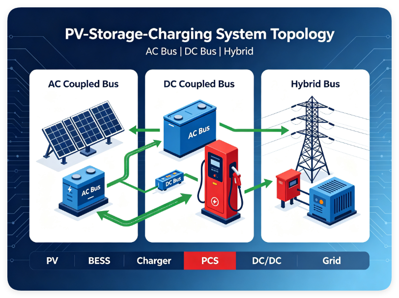
Design Considerations: How to Select the Right Topology
Factor 1: Project Scale and Annual Throughput
The efficiency advantage of DC-coupled scales with energy throughput. For a small commercial site with 100,000 kWh/year consumption, a 3% efficiency gain saves 3,000 kWh—worth perhaps $330/year. The premium for DC equipment may not be justified. For a large highway service station with 2,000,000 kWh/year throughput, the same 3% gain saves 60,000 kWh—worth $6,600+ annually, justifying a significant upfront premium.
Factor 2: Existing Infrastructure
If you’re retrofitting an existing AC charging station, AC-coupled is the natural choice—add storage PCS and battery to the existing AC bus with minimal disruption. DC-coupled requires replacing chargers or adding DC/DC converters to each charger, a significantly larger capital and operational disruption.
For greenfield projects, DC-coupled offers the cleanest, most efficient design from day one.
Factor 3: Team Capability
AC equipment is universally understood by electrical engineers and technicians. DC systems at 1000V+ require specialized knowledge of DC protection, arc fault detection, and DC/DC converter control. If your O&M team lacks DC expertise, the AC-coupled topology may be the lower-risk choice despite its efficiency penalty.
Factor 4: Future Expansion Plans
If you anticipate significant expansion—adding more PV, more storage, or more DC fast chargers—the hybrid topology offers the greatest flexibility. You can start with AC-coupled for immediate deployment and add DC-coupled elements as the site grows, with the bidirectional interconnecting converter managing the interface.
Recommended Engineering Approach
🔹 For Small to Medium Charging Stations (5–10 chargers, <500 kWh storage)
Recommendation: AC-Coupled. Lowest upfront cost, fastest deployment, simplest O&M. Typical configuration: 50kW–100kW PV + 100kWh–200kWh storage + 30kW–125kW PCS.
🔹 For Large Fast-Charging Stations (10+ chargers, >1 MWh storage)
Recommendation: DC-Coupled. Efficiency advantage delivers maximum value at scale. Typical configuration: 200kW+ PV + 500kWh+ storage + 125kW–500kW PCS.
🔹 For Complex Sites with Mixed AC/DC Equipment
Recommendation: Hybrid. Best for highway service areas, large commercial complexes, industrial parks requiring both AC and DC charging capabilities.
⚡ Designing a PV-Storage-Charging System?
IMAXPWR engineering team can help evaluate your technical requirements and provide a customized solution.
Common Mistakes to Avoid
❌ Mistake 1: Sizing PCS Based Only on Battery Capacity
Many projects size the PCS simply by dividing battery capacity by desired discharge hours (e.g., 200kWh / 2h = 100kW). This ignores the peak power demand of charging stations—multiple DC fast chargers starting simultaneously can create instantaneous loads far exceeding average power.
Engineering fix: Size PCS for peak load, not average load. Add 15%–20% margin above the calculated maximum simultaneous charger load.
❌ Mistake 2: Neglecting EMS Real-Time Scheduling Capability
Some projects rely on fixed “charge at night, discharge during peak” schedules without integrating real-time PV generation and load forecasting. The result: batteries discharging during peak solar hours, or running empty during unexpected high-demand periods.
Engineering fix: Deploy an EMS with day-ahead planning + real-time adjustment capability. The system should continuously optimize based on PV forecast, load prediction, and real-time tariff signals.
❌ Mistake 3: “One-Size-Fits-All” Topology Selection
Some developers default to AC-coupled because “that’s what we always use,” missing efficiency opportunities. Others chase DC-coupled for the efficiency gains without assessing their team’s capability to maintain DC systems.
Engineering fix: Conduct a full lifecycle cost analysis before selecting topology. Evaluate four dimensions: initial investment, operating efficiency, maintenance cost, and expansion capability. Let data—not habit—drive the decision.
Frequently Asked Questions
Q: What is the actual efficiency difference between AC-coupled and DC-coupled BESS?
Real-world data shows DC-coupled systems achieve 92%–98% round-trip efficiency versus 85%–94% for AC-coupled. The gap is typically 3%–5%, with some configurations showing up to 10% difference. The efficiency advantage comes from eliminating multiple AC/DC conversion stages.
Q: How much more does a DC-coupled system cost than AC-coupled?
DC-coupled systems typically carry a 15%–25% upfront premium over AC-coupled for equivalent capacity, primarily from DC protection equipment, DC/DC converters and more sophisticated controls. However, DC-coupled can reduce BOS equipment costs by 10%–15% for new builds by eliminating separate inverters. For large-scale projects (>1 MWh), the efficiency savings typically recover the premium within 2–3 years of operation.
Q: Can I retrofit an existing AC charging station to DC-coupled?
Yes, but with significant effort. Retrofitting to DC-coupled requires replacing existing AC chargers with DC chargers or adding DC/DC converters to each charger. The simpler retrofit path is AC-coupled—adding storage PCS and battery to the existing AC bus. If your site is planning a major equipment refresh, that’s the right time to consider DC-coupled conversion.
Q: What is the payback period for a PV-storage-charging system?
Payback varies by project scale, tariff differential and solar resource. A typical small commercial site (5 × 60kW chargers + 50kW PV + 100kWh storage) achieves 2.5–3 year payback with IRR of 20%–25%. In regions with wide peak-valley tariff spreads (e.g., Guangdong, Zhejiang), payback can shorten to under 2 years.
Q: Which topology is best for a highway service area with 12 DC fast chargers?
For 10+ DC fast chargers with high annual throughput, DC-coupled is typically the optimal choice. The 3%–5% efficiency gain delivers maximum value at scale. If the site also has existing AC loads or AC chargers that must be retained, consider the hybrid topology to accommodate both.
About IMAXPWR
ImaxPWR (Imax Power Technology Co., Ltd.) is a national high-tech enterprise specializing in new energy solutions. As an OEM/ODM manufacturer, IMAXPWR focuses on energy storage power conversion equipment, bidirectional PCS, DC/DC converters, V2G modules, energy storage cabinets and integrated microgrid solutions.
With strong R&D capabilities and power electronics expertise, IMAXPWR provides reliable energy conversion solutions for global customers in industrial and commercial energy storage, renewable energy integration and smart microgrid applications.
IMAXPWR’s product portfolio includes:
-
- Grid-Forming & Grid-Following PCS — 30kW to 500kW, 400V/690V AC
- Bidirectional DC/DC Converters — SiC technology, up to 99% efficiency, 500V–1500V DC
- V2G Modules — Bidirectional AC-DC for vehicle-to-grid applications
- Energy Storage Cabinets — Integrated BESS solutions for C&I applications
- Microgrid Solutions — Complete energy management for island and weak-grid sites
All products are CE, UL and ROHS certified, serving markets across Europe, Asia, North America, Australia, the Middle East, Korea and Japan.
🔋 Need a Technical Solution for Your Project?
IMAXPWR engineering team can assist from equipment selection to system design.
Related Reading
- MPPT Charge Controller Selection Guide: 5 Core Specs — how to evaluate efficiency, MPPT voltage window, protection, scalability, and total cost of ownership.
- DC-DC Converter Troubleshooting Guide: 6 Common Faults — root causes and field fixes for PV-storage-charging systems.