

Description
Abstract
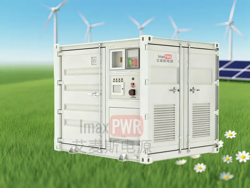
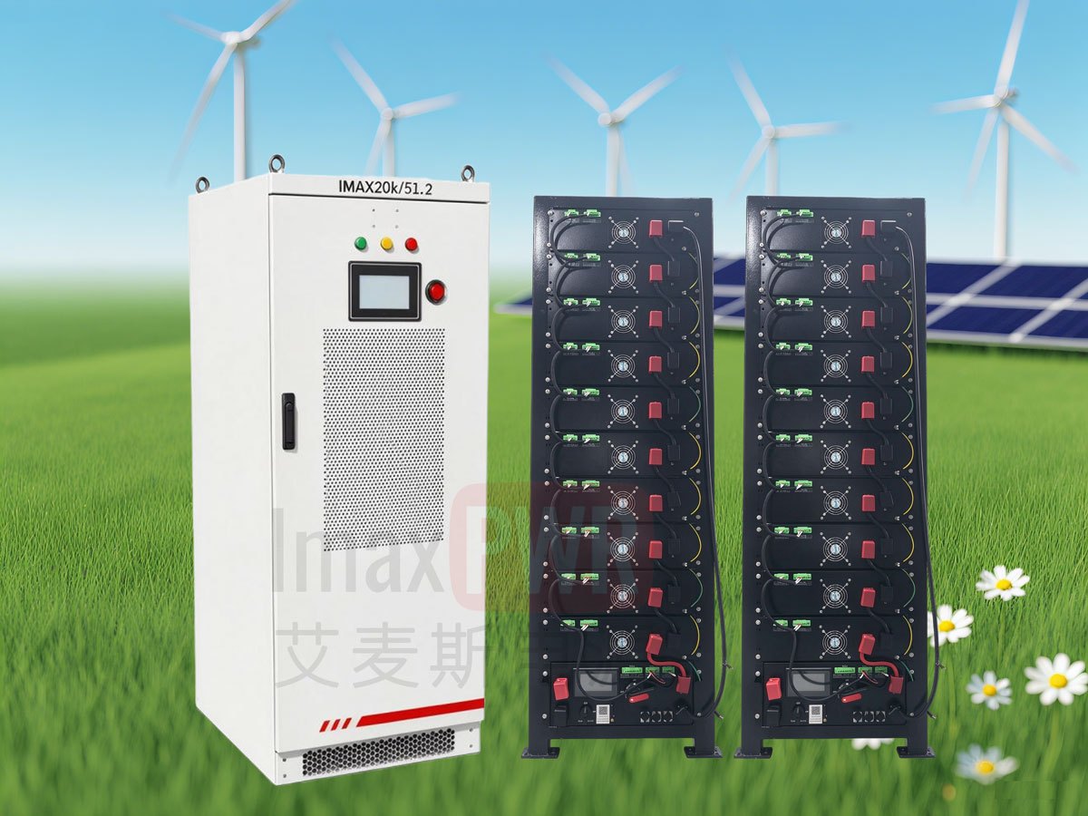
The IMESS-22P20M51.2 is a 20 kW / 51.2 kWh wind-solar-storage system built as two separate cabinets rather than one enclosure: an electrical cabinet that carries the power conversion and control chain, and a battery cabinet that carries the LiFePO4 storage. The electrical cabinet integrates PCS, MPPT, EMS, DCDC, AC/DC distribution and surge protection; the battery cabinet holds ten 5.12 kWh modules wired 1P160S, giving a rated 51.2 kWh at 512 Vdc nominal. Measured module figures are 99.2% peak efficiency for the 66 kW DCDC module and >99.5% MPPT efficiency above 5000 W of array input. The system is specified for -30 to 60 °C operation, below 95% relative humidity, and altitudes up to 4000 m, which places it in the class of installations where a diesel generator would otherwise run continuously: remote construction sites, mining camps, islanded loads and emergency backup. Because the two cabinets are matched at the factory, on-site work is limited to the inter-cabinet DC bus, the communication link and earthing. Every figure in this page is taken from the product user manual V1.1 and the battery cabinet manual V1.1.
1. Product positioning
Most off-grid packages sold today are assembled on site from a PV inverter, a separate battery bank and a third-party controller. The IMESS-22P20M51.2 takes the opposite route: the conversion chain and the storage are delivered as one matched pair of cabinets from a single manufacturer. The practical consequence is that the DC bus voltage, the communication protocol and the protection thresholds are already coordinated before the equipment leaves the factory, and the site team is not left to reconcile three vendors’ settings.
The design target is a site with no reliable distribution network, a load in the tens of kilowatts, and no permanent maintenance staff. That is why the system ships with an LED touchscreen showing charge-discharge throughput and operating mode, a three-colour RUN / ALARM / FAULT indicator set and a physical emergency stop, instead of relying on a remote SCADA connection that may not exist.
2. System architecture
2.1 Electrical cabinet
According to the product user manual V1.1, the electrical cabinet integrates PCS, MPPT, EMS, DCDC, AC/DC distribution and surge arresters. The MPPT module accepts 260-900 Vdc from the PV array and regulates the DC bus at 150-750 Vdc; the DCDC module sits between that bus and the battery string, with a battery-side window of 180-1000 Vdc and a 600 Vdc nominal bus side; the PCS performs the bidirectional conversion between the DC bus and the AC side. The EMS allocates power across the three paths.
2.2 Battery cabinet
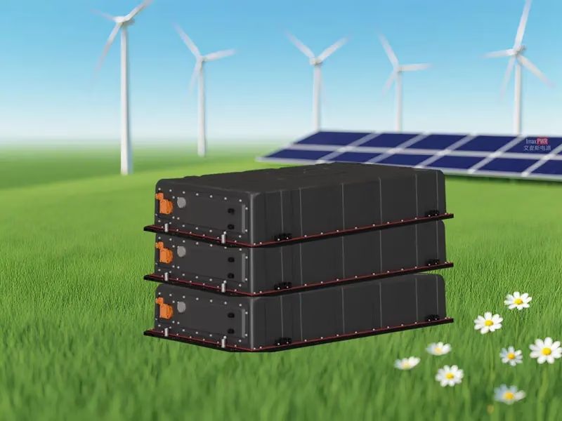
The battery cabinet carries a rack, ten 5.12 kWh modules and a high-voltage box. Cells are first series-connected into standardised modules; modules are then series-connected and combined at the HVB to form a string that feeds the PCS. Each module carries its own BMU, fan and aerosol fire-suppression device and reports cell voltage and temperature over a daisy-chain link, so a single failed module can be replaced without returning the whole string.
MPPT window: 260-720 Vdc
Max input: ≤41 A
Output: 150-750 Vdc / 0-50 A
MPPT efficiency: >99.5%
Range: 180-1000 Vdc
Links MPPT / DCDC / PCS
Battery side: 180-1000 Vdc
Peak efficiency: 99.2%
512 Vdc nom. / 464-576 Vdc
10 × 5.12 kWh modules
AC parameters: per project
Islanded or grid-tied
3. Technical specifications
All values below are reproduced from the product user manual V1.1 and the battery cabinet manual V1.1. No figure has been converted or estimated.
3.1 DCDC module M66KDC
| Parameter | Value |
|---|---|
| Battery-side voltage range | 180-1000 Vdc |
| Battery-side nominal / full-load range | 350 Vdc / 350-1000 Vdc |
| Battery-side max. current | 189 A |
| Bus-side nominal / rated current | 600 Vdc / 110 A |
| Rated power | 66 kW |
| Topology / peak efficiency | Non-isolated / 99.2% |
| Protection grade / cooling | IP20 / intelligent forced air |
| Operating temperature | -30 to 60 °C (over-temp above 45 °C) |
| Dimensions (W×D×H) / weight | 440×535×86 mm / 13 kg |
| Interfaces | RS485, CAN, Ethernet, dry contact |
| Applied standards | GB/T 34120-2023, GB/T 34133-2023, EN 62477, EN IEC 61000 |
3.2 MPPT module
| Parameter | Value |
|---|---|
| Nominal / input voltage range | 710 Vdc / 260-900 Vdc |
| MPPT operating / full-load window | 260-720 Vdc / 600-720 Vdc |
| Start voltage / max. input current | 325 Vdc / ≤41 A |
| MPPT efficiency | >99.5% (MPP ≥5000 W) |
| Output voltage / current | 150-750 Vdc / 0-50 A (limit settable) |
| Conversion efficiency | ≥95.8% at 750 V, 50-100% load, 710 V input |
| Voltage / current regulation | <±0.5% / ≤±1% (20-100% load) |
| Standby power | 9 W at 600 Vdc input |
| Operating temperature | -40 to +75 °C (derate above 50 °C) |
| Protection grade / parallel MPPT | IP20 / up to 2 modules |
3.3 Battery system (ESS HVA 51.2 kWh)
| Parameter | Value |
|---|---|
| Cell chemistry | LiFePO4, prismatic aluminium case |
| Module / quantity | GS HVA-5.12 kWh × 10 |
| Series-parallel / rated capacity | 1P160S / 100 Ah |
| Rated energy | 51.2 kWh |
| Nominal voltage / range | 512 Vdc / 464-576 Vdc |
| Max. charge / discharge current | 50 A |
| Module weight | 55 ±3 kg per module |
| Protection grade / cooling | IP20 / split cooling |
| Operating temperature / humidity | -10 to +50 °C / 5-95% |
| Altitude | <4000 m (derate above 2000 m) |
3.4 Whole-system environment
| Item | Requirement |
|---|---|
| Ambient temperature | -30 to 60 °C (derate above 45 °C) |
| Humidity | <95%, non-condensing |
| Altitude | 4000 m (derate above 2000 m) |
MPPT module — 260-900 Vdc array input
DCDC M66KDC — 66 kW, 99.2% peak
EMS controller
AC/DC distribution unit
Surge arresters
LED touchscreen + RUN / ALARM / FAULT
Emergency stop button
10 × GS HVA-5.12 kWh modules
Per module: 16 cells + 1 BMU + 1 fan + aerosol suppression
High-voltage box (HVB), 157 A rated
Current sampling -250 to 250 A
Voltage sampling 0-1500 V
String: 1P160S, 512 Vdc nominal
4. Core advantages
4.1 Fewer conversion stages on the PV path
PV enters through the MPPT module and lands directly on the 600 Vdc bus; the battery hangs on the same bus through the DCDC module. Compared with an AC-coupled arrangement, where PV is inverted to AC and then rectified back to DC for storage, the DC-coupled path removes one full AC/DC conversion. The module-level figures behind that claim are 99.2% peak DCDC efficiency and MPPT efficiency above 99.5% at 5000 W or more of array input.
4.2 Maintenance granularity down to 5.12 kWh
The string is built from ten identical 5.12 kWh modules, each 55 ±3 kg and each carrying its own BMU and aerosol suppression device. A module that reports an abnormal cell can be swapped on site rather than pulling the whole string; the remaining nine keep the site supplied at reduced capacity instead of taking it dark.
4.3 Wide DC windows on both sides
The DCDC module holds full load from a 350 Vdc battery up to 1000 Vdc, and the MPPT module regulates from 260 Vdc to 900 Vdc of array input with a full-load window of 600-720 Vdc. That spread is what lets one cabinet SKU serve both a short string on a hot roof and a long string at altitude, without a hardware change.
4.4 Designed for unattended sites
The DCDC module covers over-voltage, under-voltage, over-current, high-side short circuit, over-temperature, insulation-resistance monitoring, surge and DC reverse polarity. Combined with the aerosol suppression inside every module and the physical emergency stop, the protection set targets sites where the nearest technician is hours away. Acoustic noise stays at or below 65 dB, so the cabinets can sit beside a work area rather than behind a fence.
5. Application scenarios
The user manual names four application classes. They map onto the following field conditions:
- Backup power — long standby duty, with the battery feeding the PCS when the grid drops.
- Emergency power — 220/380 V AC output for repair and rescue crews in place of a diesel set.
- Wind-solar-storage — PV as the primary source, battery as the buffer, forming a microgrid unit independent of the distribution network.
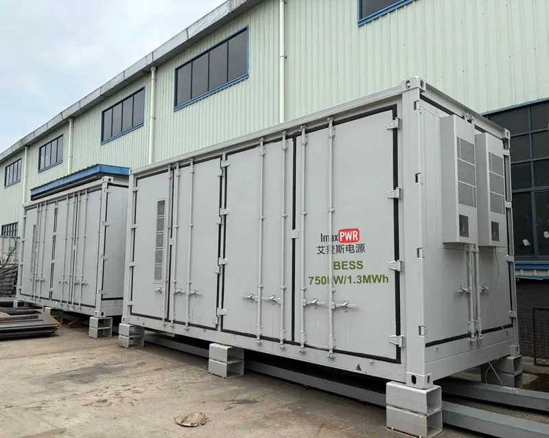
- Remote construction — mining camps, pipeline spreads and road works with no grid connection, where the two cabinets move as a unit by forklift or crane.
6. Protection and safety
The cabinet carries lethal DC voltage. The manual restricts all work to qualified electricians, requires “do not close” tags at every upstream switch and a warning tape around the work area. After shutdown the AC and DC supplies must be isolated and at least 15 minutes allowed before the front door is opened; the internal busbars must then be proved dead with a multimeter. During battery inspection, cell temperature has to fall below 40 °C before a technician may approach, and the unit must not be disposed of as ordinary waste.
7. Frequently Asked Questions (FAQ)
Q1: How many cabinets does the system comprise?
Two. Cabinet one is the electrical cabinet, integrating PCS, MPPT, EMS, DCDC, AC/DC distribution and surge arresters. Cabinet two is the battery cabinet, holding the rack, ten 5.12 kWh modules and the high-voltage box. Site work covers the inter-cabinet DC bus, the communication link and earthing.
Q2: What is the battery capacity and configuration?
51.2 kWh rated, LiFePO4, built from ten 5.12 kWh modules in a 1P160S string: 100 Ah rated capacity, 512 Vdc nominal, 464-576 Vdc operating window, 50 A maximum charge and discharge current.
Q3: Which energy sources can the system accept?
The manual states PV and battery as the documented inputs. The MPPT module accepts 260-900 Vdc from the array, and the battery connects bidirectionally through the DCDC module. Wind generation, where required, is configured against the project technical agreement rather than a fixed catalogue option.
Q4: Can it operate in hot or high-altitude locations?
Yes, with derating. The whole system runs from -30 to 60 °C and derates above 45 °C; altitude is 4000 m with derating above 2000 m. The battery cabinet itself is rated -10 to +50 °C and below 4000 m, so the enclosure interior has to stay inside that band.
Q5: What is required before opening the cabinet?
Isolate both the AC and DC supplies, wait at least 15 minutes, then measure the internal busbars with a multimeter to confirm they are dead. Keep the escape route clear throughout the work, and dispose of the unit through an authorised recycler.
8. Related Products
- IMAX HV-AIO Series 15kW/51kWh all-in-one hybrid storage — single-enclosure alternative for smaller loads.
- Imax Power wall-mounted hybrid MPPT controller 60-320 kW — PV side only, for retrofits onto an existing bank.
- BAC-1K0110 bidirectional AC/DC module 62.5 kW / 1000 Vdc — the PCS building block for cabinet-level designs.
- IMAX HV-DC Series 80-160 kWh rack-mounted cabinet — larger battery tier where 51.2 kWh is not enough.
- Full energy storage systems range — PCS, DC/DC, ESS cabinets and STS/PCM in one index.
Reference standards: National Standards Full-Text System (GB/T 34120, GB/T 34133) · IEC Webstore (EN 62477, EN IEC 61000) · International Energy Agency (storage statistics)
About the Author
Ethan Li, energy storage systems engineer at ImaxPWR Power Co., Ltd., with years of experience in PCS, DC/DC converters, BESS, and microgrid design. He has participated in multiple domestic and international energy storage projects in solution design and technical support.
ImaxPWR is a National High-Tech Enterprise and a source manufacturer of integrated energy storage products and system solutions. This article was reviewed by Ethan Li.
About ImaxPWR
ImaxPWR Power Co., Ltd. (Brand: ImaxPWR) is a National High-Tech Enterprise and source manufacturer, covering bidirectional converters, DC/DC, energy management, and energy storage cabinet integration, providing design, delivery, and O&M services. Products are CE, UL, and ROHS certified. The IMESS-22P20M51.2 sits in the off-grid tier of that range, pairing a 51.2 kWh LiFePO4 battery cabinet with an integrated conversion cabinet for sites beyond the reach of a distribution network.
Sizing an off-grid system for a site with no grid connection?
Send us the load profile, daily kWh demand, planned PV capacity and the number of consecutive overcast days. We will come back with the battery capacity and cabinet configuration for the site.
Contact: COCO
Tel / WhatsApp: +86-13760212825
Email: info@imaxpwr.com
Website: https://imax-pwr.com
© 2026 ImaxPWR Power Co., Ltd. · This page is for product introduction purposes. Specifications are taken from the IMESS-22P20M51.2 user manual V1.1 and the battery cabinet manual V1.1; where a contract technical agreement differs, the agreement prevails.