

Abstract
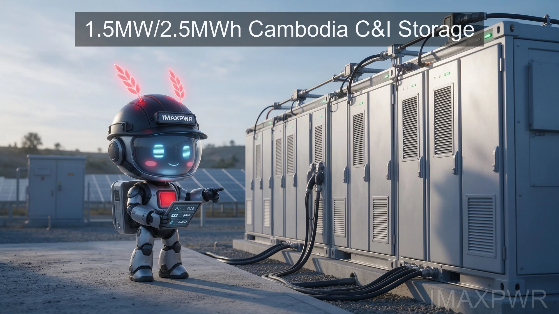
A manufacturing customer in Cambodia operates an injection molding line that cannot tolerate power interruptions. ImaxPWR delivered a 1.5MW / 2.5MWh commercial and industrial (C&I) energy storage system with 12 parallel 125kW PCS modules, 6 × 120kW MPPT solar chargers, and 3 × 600kW grid-tied/off-grid transfer switches. The cluster-level DC-coupled architecture keeps production running through grid outages, shifts load to solar and battery during peak tariff hours, and provides UPS-grade backup for critical injection molding equipment. The system was commissioned in 2025.
1. Project Overview
The customer is an industrial injection molding plant in Cambodia, Southeast Asia, running continuous-production plastic molding machines that are sensitive to voltage sags and short outages. Per IRENA, Cambodia’s grid reliability in industrial zones remains uneven, with voltage fluctuations and scheduled outages that can scrap in-progress molding cycles and damage machine tooling.
| Parameter | Value |
|---|---|
| Location | Cambodia (Southeast Asia) |
| Industry | Injection molding manufacturing |
| PCS capacity | 1.5 MW (12 × 125kW) |
| Battery capacity | 2.5 MWh |
| Solar MPPT | 6 × 120kW (720kWp array coupling) |
| Transfer switches | 3 × 600kW grid-tied/off-grid |
| Operating mode | Grid-tied with seamless off-grid backup |
| Commissioned | 2025 |
2. Project Challenges
2.1 Weak Grid and Interruption Risk
Cambodia’s industrial grid outside Phnom Penh experiences voltage sags, frequency drift, and scheduled load-shedding. An injection molding cycle that drops mid-injection can scrap a multi-kilogram plastic part and may damage screw and barrel components. The customer required a ride-through time measured in tens of milliseconds, not seconds, and a clean sine wave on the off-grid bus to protect servo-driven molding machines.
2.2 Inrush and Non-linear Loads
Injection molding machines draw high inrush current when hydraulic pumps start, and their heaters and servo drives generate non-linear load harmonics. A PCS sized only to continuous kW rating would trip on motor startup. The solution had to handle peak overload without dropping offline, and the DC bus had to absorb harmonic distortion without voltage instability.
2.3 Tropical Climate
Southeast Asian industrial zones combine high ambient temperatures (up to 40°C), high humidity, and dust. Per IEC 61000 and IEC 62619 requirements, the PCS and battery cabinet had to maintain rated output at high temperature without aggressive derating, and the enclosure had to resist humidity and conductive dust.
3. Engineering Analysis
The daily load profile of the molding line peaks during two production shifts. Load calculation sized the PCS at 1.5 MW to cover the combined running load plus a 20% margin for motor inrush. The 2.5 MWh battery bank was sized to provide roughly 1.5 to 2 hours of autonomous operation at rated load, enough to ride through scheduled outages and complete the in-progress molding cycle. Per IEA, industrial PV self-consumption in Southeast Asia improves economics when solar generation aligns with daytime production shifts, which dictated a DC-coupled architecture rather than an AC-coupled one.
720kWp solar input
DC bus coupling
6 clusters, each cluster
2 × 125kW PCS + 1 × 120kW MPPT
3 × 600kW transfer switches
Injection molding load + mains
3.1 Battery Sizing and Cycle Life
The 2.5 MWh battery bank uses LFP cells at a depth of discharge (DoD) of 80%, which the EMS enforces as a hard limit to preserve cycle life over the project’s design horizon. For an industrial customer running two shifts, the battery supports one full charge-discharge cycle per day, which is well within the cycle life envelope of LFP chemistry used in stationary storage. The cluster layout places each battery block within arm’s reach of its PCS, keeping DC cable runs short and resistive losses low.
3.2 Why DC Coupling Over AC Coupling
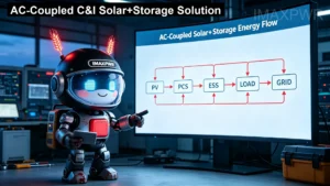
In an AC-coupled design, the PV inverter, battery inverter, and grid are connected on the AC bus, requiring an extra conversion stage between PV and battery. In this project the MPPT chargers feed the battery DC bus directly. Per IEA guidance on industrial PV+storage, DC coupling raises round-trip efficiency by reducing conversion losses, which matters for a factory whose daytime load profile aligns with solar output. The trade-off is that the DC bus must be designed carefully for fault clearance, which is why each cluster has its own DC protection and monitoring.
The cluster design groups the plant into independent power blocks. Each cluster integrates two 125kW PCS units with one 120kW MPPT on a shared DC bus. If one cluster trips or requires service, the remaining clusters continue feeding the critical load. This is more resilient than a single large central PCS, which would take the entire molding line offline on a single fault.
4. Solution Design
4.1 Equipment List
| Equipment | Quantity | Role |
|---|---|---|
| 125kW bidirectional PCS | 12 | Inverter / rectifier, parallel AC output |
| 120kW MPPT DC/DC | 6 | PV charge, cluster DC bus |
| 600kW transfer switch | 3 | Grid-tied/off-grid seamless switching |
| LFP battery cabinet | 6 clusters | 2.5 MWh storage, per-cluster protection |
| EMS controller | 1 | Cluster coordination, peak shaving, anti-reverse-power |
4.2 Control Strategy
The EMS manages three operating states. In grid-tied mode, the plant draws from the mains, the PCS charges the battery, and the MPPT feeds daytime PV to the battery and load. On grid loss, the 600kW transfer switches open in milliseconds, and the cluster PCS forms an off-grid island that continues feeding the molding line. On peak shaving, the battery discharges during high-tariff hours to cut demand charges. The EMS also prevents reverse power export to the utility, which is required under Cambodian grid connection rules for behind-the-meter C&I installations.
5. Implementation and Results
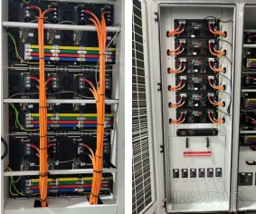
The system was engineered, delivered, and commissioned in 2025. Commissioning included cluster-by-cluster DC-bus isolation checks, transfer-switch timing tests, and off-grid islanding drills under real molding loads. The on-site cabinet layout uses front-access cabling for maintenance in a tropical factory environment.
| Metric | Before Storage | After Storage |
|---|---|---|
| Critical load on grid outage | Drops immediately | Rides through via islanding |
| Mid-cycle molding scrap | Frequent on outages | Eliminated |
| Peak-hour grid draw | Full utility peak demand | Shaved by battery discharge |
| PV self-consumption | Limited | Boosted by DC coupling |
6. Key Takeaways
- Cluster design beats central PCS for critical loads. Splitting the plant into six independent clusters isolates faults and keeps production running when one block requires service.
- DC coupling improves PV economics. Bypassing an extra AC conversion stage raises round-trip efficiency, especially where daytime solar matches the production schedule.
- Transfer-switch sizing matters. Three 600kW switches were specified instead of one oversized unit to keep switching independent per cluster and avoid a single-point failure.
- Tropical ratings are non-negotiable. PCS and battery cabinets must maintain rated output at 40°C+ ambient without aggressive derating; this is a common procurement error in Southeast Asia.
- Anti-reverse-power is a local requirement. Behind-the-meter C&I storage in Cambodia must be configured not to export to the utility; the EMS enforces this as a hard limit.
7. Frequently Asked Questions (FAQ)
Q1: How does the system handle a sudden grid outage?
The 600kW transfer switches detect grid loss and open within milliseconds, while the cluster PCS forms an off-grid island. Injection molding machines ride through the transition without a full shutdown, protecting tooling and unfinished parts.
Q2: Why use six clusters instead of one 1.5MW central PCS?
A single central PCS is a single point of failure. The cluster design groups 2 PCS + 1 MPPT per DC bus, so a fault on one block does not stop the entire molding line. It also simplifies maintenance and allows staged capacity expansion.
Q3: Can this configuration work in other Southeast Asian countries?
Yes. The cluster DC-coupled architecture is transferable across Cambodia, Thailand, Vietnam, and Indonesia, where weak grids, high ambient temperatures, and growing industrial PV adoption are common. Local grid-code settings and anti-reverse-power limits are configured per country.
Q4: What battery chemistry is used and why?
LFP (lithium iron phosphate) chemistry is used for its thermal stability, long cycle life, and compliance with IEC 62619 battery safety requirements — important for an indoor industrial installation in a hot climate.
Q5: What maintenance does the system require?
Routine maintenance focuses on cabinet air filters, fan health, and thermal imaging of busbar connections, on a quarterly schedule. The EMS logs fault codes and runtime hours for every PCS and MPPT, so preventive replacement can be planned before a component fails. Remote monitoring via the cloud platform gives the local team early warning before an outage affects production.
Related Reading
Related:
C&I Energy Storage Products ·
Bidirectional PCS Modules ·
Hybrid PCS and Microgrid Solutions
About the Author
Ethan Li, energy storage systems engineer at ImaxPWR Power Co., Ltd., focused on PCS, DC/DC, and microgrid design for C&I and telecom storage projects. Reviewed by Ethan Li.
About ImaxPWR
ImaxPWR Power Co., Ltd. is a National High-Tech Enterprise and source manufacturer of bidirectional converters, PCS, DC/DC modules, and integrated energy storage cabinets, serving industrial, telecom, and microgrid customers across Southeast Asia, Africa, and Latin America. Products comply with IEC standards and are CE, UL, and ROHS certified.
Planning a similar C&I storage or microgrid project in Southeast Asia?
Submit your load profile, grid conditions, and target capacity for a cluster-design proposal and system sizing.
Contact: COCO
Tel / WhatsApp: +86-13760212825
Email: info@imaxpwr.com
Website: https://imax-pwr.com
© 2026 ImaxPWR Power Co., Ltd. · This is an engineering case study. Project details are anonymized; data sourced from IEC, IRENA, and IEA public references.