

Abstract
For commercial and industrial (C&I) sites that already operate rooftop PV, an AC-coupled solar + storage solution is the lowest-risk way to add a battery energy storage system (BESS) without touching the existing PV inverters. In this architecture the PV inverters and the storage PCS units connect independently to a shared AC bus, while an energy management system (EMS) coordinates generation, storage, load, and grid exchange through the communication network. According to the IEA, global battery storage additions reached 108 GW in 2025, up about 40% year-on-year, and a large share of new C&I systems are now designed as AC-coupled retrofits because they decouple storage sizing from the existing PV plant. This article explains the system topology, the three main EMS operating modes (self-consumption, PV priority, and load priority), the engineering trade-offs versus DC-coupled and hybrid topologies, and a recommended equipment configuration based on ImaxPWR C&I storage cabinets and PCS units. It is written for plant owners, EPC contractors, and consultants in Southeast Asia, South Asia, the Middle East, Africa, and Latin America, where grid stability, ambient heat, and voltage fluctuation make system design choices critical.
1. Solution Overview
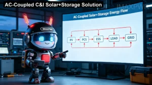
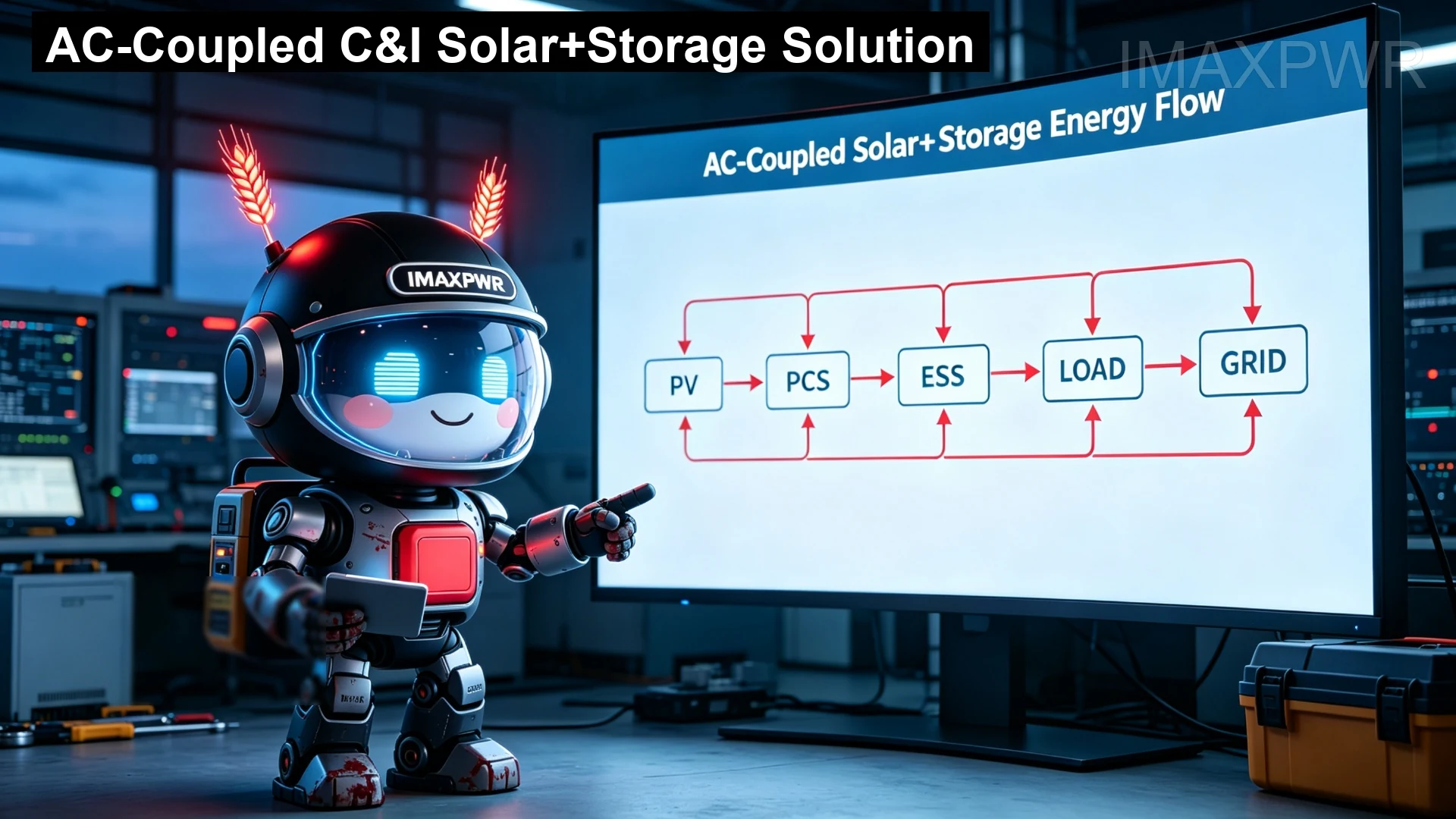
An AC-coupled C&I solar + storage solution connects the photovoltaic system and the battery energy storage system in parallel at the AC busbar. The PV array feeds a PV inverter (or several), the battery bank connects through a bidirectional PCS, and both exchange power with the site AC bus. The EMS monitors the grid meter, the loads, PV output, and battery state, then issues operating commands to maximise solar self-consumption and reduce electricity cost. Because the storage branch is electrically independent of the PV branch, the battery capacity and PCS power can be sized, added, or expanded later without redesigning or replacing the existing PV installation.
Per IEC 62933-5-1:2024, grid-integrated electrical energy storage systems must be designed with explicit safety considerations covering hazard identification and risk mitigation across the full system; the AC-coupled architecture supports this because each storage unit can be isolated and protected at the PCS and at the AC connection point independently of the PV side. Based on CNESA DataLink 2025 annual data, China alone added 66.43 GW / 189.48 GWh of new energy storage in 2025, up 52% / 73% year-on-year, and user-side installations (of which C&I storage is the majority) have been the fastest-growing segment. Globally, solar PV additions exceeded 600 GW in 2025, pushing cumulative capacity to about 2,800 GW — the same drivers — high daytime PV surplus, rising grid-import prices, and falling battery costs — apply across emerging markets, making AC-coupled retrofits a practical entry point for C&I customers.
2. Why AC-Coupled for Sites with Existing PV
The typical C&I pain points that this solution addresses are the same across markets:
- Low self-consumption: daytime PV output exceeds on-site load, so surplus power is exported at low or zero value while the plant still imports power at night at retail tariffs.
- Export constraints: many utilities in emerging markets cap or penalise grid export, forcing plants to curtail PV and waste cheap solar energy.
- Expansion without replacement: retrofitting storage into an existing PV plant via DC coupling would require replacing or re-wiring the PV inverters; AC coupling avoids this entirely.
- Flexible capacity: storage can be added in phases, and the PCS branch can also support PV-storage-charging or backup scenarios later.
For sites with existing PV, AC coupling is therefore the lowest-disruption upgrade path: the storage system behaves as a controllable load and source at the AC bus, and the EMS handles coordination in software rather than in hardware modifications.
3. System Architecture
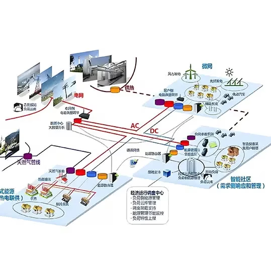
The architecture shown in the topology diagram below contains three networks: the AC bus (black, power), the DC bus (red, battery and PV DC sides where relevant), and the communication network (green, EMS control). The grid connection point, the site loads, the PV inverters, and the storage PCS units all terminate on the AC bus. Two parallel PCS units and two battery clusters are shown, but the design is modular — additional PCS and battery banks can be added to the same AC bus when capacity needs to grow.
Key functional roles:
- EMS: the system controller. It reads the grid meter, PV meters, battery BMS, and load data, then dispatches charging/discharging commands to the PCS units.
- PCS (storage): bidirectional AC/DC converter between the AC bus and the battery. Multiple PCS units can be paralleled for higher power.
- Battery bank: LFP-based clusters managed by the BMS, sized for the required energy throughput and cycle life.
- Monitor: metering and monitoring point on the grid side, providing the revenue-grade data the EMS uses to decide import/export behaviour.
Because the PV inverters and storage PCS are electrically decoupled, both branches can be commissioned independently, and a fault on either side does not force the other offline. This separation is a core safety and availability advantage in weak-grid regions.
4. EMS Operating Modes
The EMS executes operating instructions for solar self-consumption and grid interaction. Three modes are most common for C&I AC-coupled systems, as illustrated in the control logic diagram:
- Self-consumption: the default mode. The battery charges from PV surplus during the day and discharges to cover evening and night load, minimising grid import without exporting PV power.
- PV priority: PV generation is used first for on-site load; the storage system absorbs excess PV that would otherwise be curtailed, raising the solar self-consumption rate.
- Load priority: the storage system prioritises serving critical loads, useful for sites where uninterrupted supply to key processes matters more than energy arbitrage.
Mode selection can be scheduled by time-of-use tariff, triggered by load events, or set manually by the operator. In practice, plants often run self-consumption during weekdays and switch to PV priority when grid export limits apply, or to load priority during outages.
5. Engineering Analysis & Key Benefits
5.1 Coupling Topology Trade-offs
The coupling topology determines how PV and battery share the DC/AC conversion chain. The table below compares the three mainstream options for C&I systems:
| Dimension | AC-Coupled | DC-Coupled | Hybrid |
|---|---|---|---|
| Retrofit to existing PV | No PV inverter changes | Requires re-wiring/DC combiner | Depends on design |
| Storage expansion | Add PCS + battery in parallel | Limited by DC bus capacity | Moderate |
| PV self-consumption rate | High with EMS modes | Very high (direct DC harvest) | Very high |
| Conversion efficiency (storage path) | One extra AC/DC stage (typical 95-97%) | Single DC/DC stage (higher) | Optimised per branch |
| Backup / off-grid capability | With STS-equipped PCS | Possible | Yes |
| Best-fit scenarios | Existing PV, AC-load-heavy sites, PV-storage-charging | New plants, high DC harvest priority | Mixed loads, complex energy flows |
The AC-coupled path trades a small efficiency loss in the storage branch (one additional AC/DC conversion) for a large gain in flexibility, retrofit simplicity, and expansion headroom. For most existing-PV C&I sites, that trade is the right one.
5.2 Key Benefits
- Flexible storage configuration: PCS power and battery energy are independently sized; a 100 kW PCS can pair with 200 kWh or 300 kWh depending on the load profile and tariff.
- Easy expansion: adding another PCS + battery cluster to the same AC bus increases capacity without disturbing the running system — a key advantage as load grows or tariffs change.
- Higher PV utilisation and economy: by shifting surplus solar into the battery, the site raises its solar self-consumption rate, cuts grid import at peak tariffs, and can defer transformer upgrades.
- Standard-compliant safety: designs following IEC 62933-5-2 and IEC 62933-5-1:2024 provide hazard identification, risk mitigation, and protection coordination at system level, with battery safety addressed per IEC 62619 for industrial lithium cells.
6. Recommended Equipment Configuration
For a typical C&I AC-coupled retrofit, ImaxPWR recommends a system-level combination: a C&I energy storage cabinet as the battery and EMS platform, paired with high-power PCS units that handle grid-tied/off-grid switching. The table below lists representative equipment and parameters (from the ImaxPWR product range):
| Item | Representative Model | Key Parameters |
|---|---|---|
| C&I Storage Cabinet | IMAXBESS 125kW/216-315kWh | 125 kW PCS rating, 216-315 kWh LFP, integrated BMS/EMS |
| Storage PCS (module) | MSP100HC | 100 kW non-isolated bidirectional AC/DC, high density |
| PCS with STS (backup-ready) | MSP100HKST / MSP125HKST | 100 / 125 kW with static transfer switch for fast grid-tie/off-grid transfer |
| EMS / Energy Management | Cabinet-integrated EMS | Self-consumption / PV-priority / load-priority modes, tariff scheduling |
A plant with 400 kWp of existing PV and a 300 kVA average daytime load, for example, would typically install a 125 kW / 261 kWh cabinet to shift two to three hours of PV surplus into the evening peak window — sizing is always confirmed against the actual load curve and tariff structure before quotation. Per IEC 62933-5-2, the electrochemical subsystem must be designed and tested against system-level safety requirements covering thermal, electrical, and abuse scenarios; LFP chemistry and cabinet-level protection address these requirements in the recommended configuration.
7. Key Takeaways
- AC coupling is the lowest-disruption way to add storage to an existing PV plant: no PV inverter replacement, no DC re-wiring, and phased expansion on the same AC bus.
- The EMS is the brain of the system; choosing the right operating mode (self-consumption, PV priority, or load priority) determines how much solar surplus is actually converted into cost savings.
- For weak-grid regions, specify PCS units with STS capability so the storage system can provide backup in addition to arbitrage, and follow IEC 62933-5-1 / 62933-5-2 / IEC 62619 in system and battery safety design.
- Size storage against the measured load curve and tariff schedule — power (kW) for the peak-shaving window, energy (kWh) for the hours that must be shifted — not against PV nameplate alone.
- AC-coupled C&I solar+storage suits three scenarios best: sites with installed PV, PV-storage-charging hubs, and plants with predominantly AC loads.
8. Frequently Asked Questions (FAQ)
Q1: Can I add battery storage to my existing PV plant without changing the PV inverters?
Yes. In an AC-coupled architecture the storage PCS connects to the same AC bus as the PV inverters, so the existing PV equipment is left untouched. The EMS coordinates the two branches through the communication network. This is the main advantage of AC coupling for retrofit projects.
Q2: What is the difference between self-consumption, PV priority, and load priority modes?
Self-consumption charges the battery from PV surplus and discharges at night to cut grid import. PV priority uses PV for load first and stores the excess that would otherwise be curtailed. Load priority makes the storage system serve critical loads first, which is useful during outages or when supply continuity matters more than arbitrage.
Q3: How is an AC-coupled C&I storage system sized?
PCS power (kW) is sized for the target peak-shaving or backup window, and battery energy (kWh) for the number of hours that must be shifted. Sizing uses the measured load curve, PV generation profile, tariff schedule, and allowed depth of discharge. ImaxPWR confirms sizing against project data before quotation.
Q4: Which safety standards apply to this system?
System-level safety follows IEC 62933-5-1:2024 and IEC 62933-5-2:2025 for grid-integrated electrochemical storage; industrial lithium cells and battery packs are addressed under IEC 62619. Regional grid codes and local regulations must also be checked at project level.
9. Related Reading
Related Reading: AC Coupled vs Series Coupled PV-Diesel-Battery Topologies · 8 C&I Energy Storage Architectures · IMAXBESS 125kW/216-315kWh Cabinet · MSP100HC 100kW PCS · MSP100HKST/MSP125HKST PCS with STS · ImaxPWR Product Center
About the Author
Ethan Li, energy storage systems engineer at ImaxPWR Power Co., Ltd., with years of experience in PCS, DC/DC converters, BESS, and microgrid design. He has participated in multiple domestic and international energy storage projects in solution design and technical support.
ImaxPWR is a National High-Tech Enterprise and a source manufacturer of integrated energy storage products and system solutions. This article was reviewed by Ethan Li.
About ImaxPWR
ImaxPWR Power Co., Ltd. (Brand: ImaxPWR) is a National High-Tech Enterprise and source manufacturer, covering bidirectional converters, DC/DC, energy management, and energy storage cabinet integration, providing design, delivery, and O&M services. Products are CE, UL, and ROHS certified. With R&D backgrounds from State Grid, XJ Group, Emerson, and Kehua Tech, ImaxPWR delivers system-level AC-coupled solar+storage solutions tailored to weak-grid and high-temperature markets.
Planning a similar BESS, energy storage station, or microgrid project?
Submit your project parameters — PV size, load curve, tariff schedule, and grid conditions — for a customized AC-coupled solar+storage solution. ImaxPWR provides design, delivery, and O&M as a source manufacturer.
Contact: COCO
Tel / WhatsApp: +86-13760212825
Email: info@imaxpwr.com
Website: https://imax-pwr.com
© 2026 ImaxPWR Power Co., Ltd. · This article is for engineering practice purposes. Data sourced from industry public materials, international standards, and engineering practice.