

30kW PV · 150kWh LFP · HI30KW Hybrid Inverter · Diesel Backup
⬇
MPPT Controller
PCS + MPPT + EMS + STS (All-in-One)
150% OL
97.8% Eff
<10ms STS
LFP Battery 150kWh
512V · 6000 cycles
AC Bus 400V/230V
Diesel Genset 100kW
↓ Control & Communication Flow (4G/CAN/RS485) ↓
▸ Battery responds in milliseconds
▸ Diesel only as emergency backup
Engineering a 30kW Solar-Storage-Diesel Microgrid for Remote Oilfield Applications
1. Project Background & Requirements
In remote oilfield operations across Northwest China’s Gobi Desert, access to reliable and cost-effective electricity remains a persistent challenge. Facilities are typically located hundreds of kilometers from the nearest utility grid, forcing operators to rely on diesel generator sets for all power needs. This dependence creates a cascade of operational and financial burdens.
The project site comprises three production wells and a field camp in the Gobi region. Key loads include three pumpjacks (22kW each), downhole pumps (15kW), and camp facilities (10kW). Maximum continuous load is approximately 55kW, with peak inrush loads exceeding 80kW during pumpjack startup. Prior to system implementation, all power was supplied by a single 100kW diesel genset operating 24/7, consuming approximately 180 liters of diesel per day with annual fuel costs exceeding USD 110,000.
The operator’s core requirements were clear: reduce diesel dependency, stabilize voltage for sensitive production equipment, minimize environmental impact, and enable remote system management without full-time on-site staff.
2. Key Engineering Challenges
Challenge 1: Extreme Environmental Conditions
The project site experiences summer surface temperatures exceeding 65°C with ambient peaks of 45°C, and winter lows of -30°C—a temperature differential of over 75°C annually. Frequent sandstorms generate high dust concentrations. Standard power electronics typically derate above 40°C, with IGBT junction temperatures accelerating degradation and reducing conversion efficiency under sustained high-temperature operation.
Challenge 2: High-Inrush Cyclic Loads
Pumpjack motors draw 3–5 times their rated current during startup, creating instantaneous power spikes exceeding 80kW. Standard inverters or generators typically trip or experience severe voltage sags under these conditions, causing production interruptions and equipment damage. The conventional diesel genset could handle these surges mechanically, but operated at only 55% load factor—a highly inefficient fuel consumption regime.
Challenge 3: Seamless Source Transition
With zero PV output during nights and overcast periods, the system must transition between PV, battery, and diesel sources without disrupting production. Pumpjacks are sensitive to power interruptions—loss of power exceeding 500ms can trigger well shutdowns and data loss. A transfer time under 20ms was specified to ensure “bumpless” switching.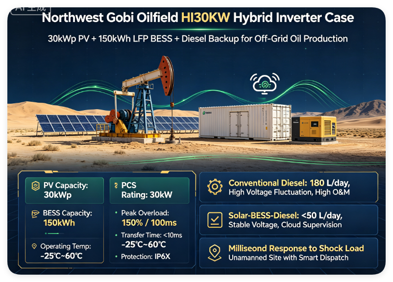
3. Engineering Analysis
The conventional diesel-only approach, while low in initial capital expenditure, presented four fundamental drawbacks: fuel transport costs exceeding USD 0.40 per kWh delivered, low generator efficiency at partial load (approximately 30%), poor voltage regulation (seconds-level response), and annual maintenance costs reaching 15–20% of equipment value.
After on-site assessment and load profiling, the engineering team established the following design parameters:
- PV capacity: 30kWp (utilizing the region’s 1,800+ annual sunshine hours)
- Storage capacity: 150kWh LFP (lithium iron phosphate) battery bank
- PCS rating: 30kW (HI30KW hybrid inverter with 150% overload capacity)
- Transfer time: <10ms for seamless source switching
PCS Sizing Logic
Formula: PCS Rating ≥ Maximum Continuous Load × Safety Factor
With a maximum continuous load of 55kW and peak inrush of 80kW (100ms duration), applying a safety factor of 1.25 yields a theoretical requirement of 68.75kW. Rather than selecting a larger-rated PCS, the engineering team opted for the HI30KW, which delivers 150% instantaneous overload capacity (45kW for 100ms) and supports parallel expansion. This approach minimized initial capital expenditure while maintaining adequate headroom for load transients.
Battery Capacity Design
Formula: Battery Energy (kWh) = Load Power (kW) × Backup Duration (h) ÷ System Efficiency
Nighttime PV outage spans approximately 12 hours, with actual load averaging 30kW (pumpjacks operating intermittently). At 90% system efficiency: 30 × 12 ÷ 0.9 = 400kWh. However, recognizing that pumpjacks do not run continuously at full load and that diesel can intervene during extended overcast periods, the team specified a 150kWh LFP battery—providing 8–10 hours of pure battery backup while maintaining expansion capability to 300kWh.
Architecture Decision: AC Coupling
The system employs an AC-coupled architecture for three reasons:
- Existing diesel genset integrates directly into the AC bus—minimal retrofit cost
- Future PV expansion or second genset can be added without major re-engineering
- Mature, field-proven topology with simpler maintenance procedures
DC coupling was considered but rejected due to the need for extensive modification of the existing distribution system and reduced flexibility for multi-source integration.
4. System Architecture
▼
MPPT
EMS
STS (<10ms)
LFP Battery Bank
150kWh · 512V
AC Bus (400V/230V)
Diesel Genset (100kW Standby)
▸ Dashed lines = Control/Communication
5. IMAXPWR Engineering Solution
Hardware Configuration
The solution centers on the HI30KW Hybrid Storage Inverter, a single integrated unit combining four core functions:
- Bidirectional PCS: 30kW rated, 150% overload for 100ms, 97.8% peak efficiency
- Dual-input MPPT: 99.8% tracking accuracy, wide 300–830V DC input range
- Integrated EMS: Real-time energy dispatch with multiple operating modes
- Static Transfer Switch: <10ms grid-to-offgrid transition
The battery bank comprises 150kWh LFP (lithium iron phosphate) cells with a nominal voltage of 512V, operating within a 10–95% SOC window. The integrated BMS provides cell-level voltage and temperature monitoring with overcharge, over-discharge, over-temperature, and short-circuit protection. LFP chemistry delivers 6,000+ cycles at 80% DOD, with a design life exceeding 10 years.
Control Strategy
The EMS executes a three-tier dispatch logic:
- Daytime: PV supplies load first; surplus charges battery; diesel remains off
- Nighttime: Battery discharges to supply load; diesel starts only when SOC falls below 20%
- Transient events: Battery responds within milliseconds to smooth load spikes, protecting diesel from inrush
Safety & Reliability Design
- Electrical protection: Overvoltage, overcurrent, overtemperature, and short-circuit protection at multiple levels
- Thermal management: Forced-air cooling with -25°C to +60°C operational range; IP6X-rated control enclosure
- Communication: CAN/RS485 interfaces with 4G cloud connectivity for remote monitoring
- System safety: Redundant protection layers including AFCI (arc fault detection) and ground fault monitoring
6. Engineering Comparison
| Parameter | Conventional Diesel-Only | IMAXPWR Microgrid Solution |
|---|---|---|
| Power Architecture | Single diesel genset only | PV + Battery + Diesel three-tier |
| Voltage Stability | >15% sag on load step; frequent pumpjack trips | THD <3%; battery response in milliseconds |
| Inrush Handling | Mechanical inertia; frequency ±5Hz deviation | 150% overload; frequency ±0.5Hz deviation |
| Daily Diesel Consumption | 180 liters/day (65,700L/year) | 50 liters/day (18,250L/year) — 72% reduction |
| Source Transfer | Manual restart; recovery >5 minutes | Automatic <10ms; load uninterrupted |
| Temperature Range | Derates above 40°C; cold-start issues | -25°C to +60°C; IP6X-rated |
| Operations & Maintenance | On-site staff required; weekly inspections | Remote cloud monitoring; unattended operation |
| Scalability | Full replacement required for expansion | Parallel up to 15 units; modular expansion |
7. Project Performance Evaluation
The system was commissioned in June 2024 and has operated continuously for over 26 months as of August 2026. Key performance metrics:
- System capacity: 30kWp PV + 150kWh LFP + HI30KW inverter + 100kW diesel standby
- Annual PV generation: ~45,000 kWh (1,800 effective sunshine hours)
- Average daily battery throughput: ~80 kWh
- Peak PCS efficiency: 97.8%
- System availability: 99.3% (total downtime <50 hours over 26 months)
- Transfer time: Consistently <10ms
- Ambient temperature range: -28°C to +46°C
Economic & Operational Benefits
- 72% diesel reduction: From 180L/day to under 50L/day; annual savings of ~47,500 liters
- Annual fuel cost savings: ~USD 58,000 (based on delivered diesel cost of USD 1.20/L)
- Maintenance cost reduction: Genset runtime reduced from 24h/day to under 4h/day; annual maintenance spend decreased by approximately 65%
- Equipment reliability: Pumpjack trips due to voltage instability reduced from 8 per month to zero
Lifecycle Cost Analysis
While the microgrid solution required a higher initial investment (approximately USD 130,000) compared to a diesel-only approach (approximately USD 35,000), the lifecycle economics are compelling:
- Annual fuel savings: USD 58,000
- Annual maintenance savings: USD 11,000
- Extended equipment life: LFP battery rated for 10+ years; genset runtime reduced by 70%
- Estimated payback period: 1.8 years
- 10-year lifecycle cost reduction: Approximately 55% compared to diesel-only
Need a Similar System for Your Site?
Whether you are planning a BESS project, an oilfield microgrid, or an off-grid industrial power system—
IMAXPWR’s engineering team can develop a custom solution based on your:
Load profile · Solar resource · Grid conditions · Site environment · Budget
Submit your project parameters → We’ll respond with a preliminary proposal within 24 hours
8. Key Engineering Lessons Learned
- Size for transient loads, not just steady-state average. The pumpjack’s 80kW startup transient (100ms) would have been missed by a conventional average-load calculation. The HI30KW‘s 150% overload capability proved essential.
- Thermal design must match the site’s extreme conditions. The -25°C to +60°C operational range and IP6X enclosure were not optional—they were mandatory for survival in the Gobi environment.
- Sub-10ms transfer time is the threshold for sensitive industrial loads. Pumpjacks and downhole pumps cannot tolerate interruptions beyond 500ms; the STS performance directly impacts production uptime.
- Remote monitoring transforms O&M economics. Cloud-based EMS reduced site visits from weekly to monthly, cutting travel costs by over 70%.
- Modularity is not a “nice-to-have”—it’s an expansion enabler. The HI30KW’s 15-unit parallel capability means future well additions can be integrated without scrapping existing equipment.
9. Common Mistakes to Avoid in Similar Projects
- Under-sizing the PCS: Choosing a PCS rated only for average load without accounting for motor inrush and future expansion leads to frequent tripping and operational frustration.
- Ignoring thermal derating: Selecting equipment rated for “standard” 40°C operation in a 45°C+ environment results in derating and premature failure. Always specify for actual site temperatures.
- Overlooking grid code requirements: Even off-grid systems may need to comply with future interconnection standards. Choose equipment with grid-forming capability from the start.
- Skipping the site survey: Load profiles vary significantly between sites. A generic design approach misses critical nuances like duty cycles and harmonic content.
- Neglecting communication architecture: Without a robust monitoring and control network, remote O&M becomes impossible. Plan the communication layer early.
Ready to Discuss Your Energy Storage Project?
IMAXPWR provides end-to-end engineering support—from conceptual design and system sizing to procurement, commissioning, and ongoing technical support.
We work with EPCs, developers, integrators, and industrial end-users worldwide.
Contact IMAXPWR
Company: Imax Power Technology Co., Ltd.
Brand: IMAXPWR
Website: https://imax-pwr.com
Email: info@imaxpwr.com
Phone / WhatsApp / WeChat: +86-13760212825
Contact Person: Coco
If you are planning a BESS project, industrial microgrid, or off-grid power system, our engineering team is ready to assist with customized solutions based on your specific requirements.
Explore more energy storage products at our Product Center.
This case study is based on a typical engineering scenario derived from IMAXPWR’s energy storage solution experience and industry application requirements. Actual project designs should be customized based on specific load profiles, grid conditions, regulatory frameworks, and site environmental factors.